Device for processing a workpiece

A technology for processing workpieces and plunger pumps, which is applied in the field of devices for processing workpieces, can solve problems such as optimal operation of unfavorable devices, and achieve the effects of improving processing results, optimizing cost-effectiveness, and optimizing service life

Pending Publication Date: 2020-09-15
HAMMELMANN MASCHFAB
View PDF10 Cites 0 Cited by
  • Summary
  • Abstract
  • Description
  • Claims
  • Application Information

AI Technical Summary

Problems solved by technology

[0007] The power output of a three-phase current motor does meet the requirements in installations that must provide a relatively large volume flow and / or include several plunger pumps arranged in parallel, but for systemic reasons can only be delayed in providing what is needed to operate the nozzles pressure, which is detrimental to optimal operation of the device

Method used


Image

  • Device for processing a workpiece

Examples


Embodiment Construction

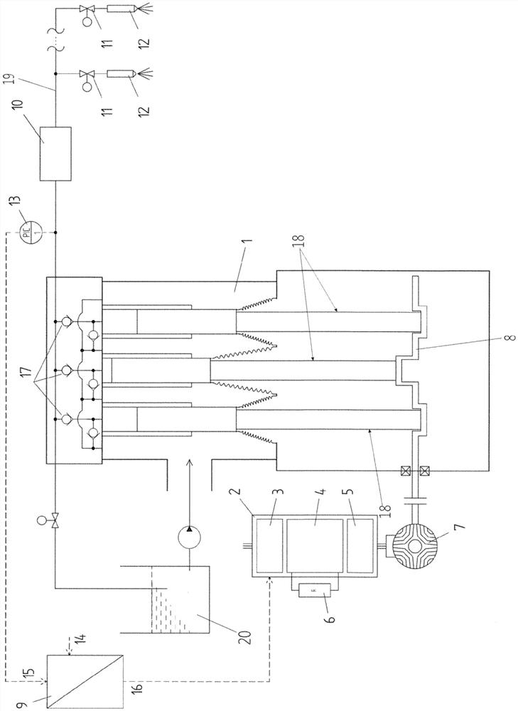
[0028] In the figures there is shown a device for machining workpieces, which has a plunger pump 1 comprising, in the example, three plungers 18 mounted on a crankshaft 8, preferably with respect to each other Offset by 120° and drivable in an oscillating manner by means of an electric motor connected to the crankshaft 8 .

[0029] The electric motor is designed as a reluctance motor 7 according to the invention and is connected to a frequency converter 2 comprising a rectifier 3 , a DC intermediate circuit 4 and an inverter 5 .

[0030] The braking resistor 6 is connected to the DC intermediate circuit 4 of the frequency converter 2, and when the reluctance motor 7 stops, the braking resistor realizes a rapid reduction of the speed of the crankshaft 8.

[0031] On the suction side, the plunger 18 is connected to a fluid accumulator 20 , while the fluid at high pressure after a working cycle of the plunger 18 is supplied in this example via a pressure line 19 into two consumer...


PUM


Abstract

A device for processing a workpiece, having at least one plunger pump (1) which can be driven by means of an electric motor and which serves for generating a highly pressurized volume flow, which volume flow can be interrupted in controlled fashion and emerges from at least one connected consumer (12), wherein the volume flow is conveyed at substantially constant high pressure via a pressure line(19) to the consumer (12), is designed such that the electric motor is designed as a reluctance motor (7) which is controllable by means of a connected frequency converter (2), wherein a pressure sensor (13) is connected to the pressure line (19), which pressure sensor is connected to a controller (9).

Description

technical field [0001] The invention relates to a device for machining workpieces according to the preamble of claim 1 . Background technique [0002] Such devices are well known. They are used, as described in EP 1 901 894 B1, for example to machine the surface of workpieces, eg to roughen or deburr them using a fluid pressure of 3000 bar to 4000 bar. Other devices for machining workpieces are known from AT 515943 A4 and AT 512 322 B1. [0003] Here, the high pressure is generated by a plunger pump comprising a plurality of plungers mounted on the crankshaft at equal angular intervals with respect to each other to generate a uniform volume flow. The drive of the crankshaft, through which the oscillating movement of the plunger is effected, takes place by means of an electric motor, usually a three-phase current motor. [0004] For the use of the device mentioned as an example, it is decisive that a substantially equal high pressure is available in the pressure line throu...

Claims


Application Information

Patent Timeline
Patent Type & Authority Applications(China)
IPC IPC(8): H02P25/08F04B17/04
CPCF04B17/04H02P25/08H02P3/065B24C1/083B24C7/0023F04B49/065F04B17/03F04B9/113
Inventor C·贝德诺兹M·格吕特M·贾尔洲
Owner HAMMELMANN MASCHFAB
Why Eureka
Try Eureka