Cooling fin structure

a technology of cooling fins and fins, which is applied in the direction of conduction heat transfer modifications, lighting and heating apparatus, and mechanical devices. it can solve the problems of reducing the cooling efficiency of electronic devices and increasing the load on motors, so as to improve the efficiency of heat transfer from the pin fins to the coolant and reduce the pressure loss in the flow of coolan

Active Publication Date: 2016-12-20
TOYOTA JIDOSHA KK +1
View PDF19 Cites 3 Cited by
  • Summary
  • Abstract
  • Description
  • Claims
  • Application Information

AI Technical Summary

Benefits of technology

[0008]The invention provides a cooling fin structure used in a cooler in which pin fins are arranged in a zigzag form, wherein a pressure loss in the flow of a coolant is reduced, while the efficiency of heat transfer from the pin fins to the coolant is improved.
[0010]With the cooling fin structure constructed as described above, each of the pin fins is provided with the irregularly shaped portions, whereby the surface area of the pin fin that contacts the coolant, and the cross-sectional area of the pin fin, are increased, as compared with a pin fin that consists solely of a circular portion. As a result, the efficiency with which heat is transferred from the pin fins to the coolant can be improved. Also, the outer peripheral surface of the irregularly shaped portions is shaped along a circumference having a center at a center point of a circular portion of a pin fin located adjacent to the pin fin having the above irregularly shaped portions, in an oblique direction relative to the direction of flow of the coolant. With this configuration, the coolant smoothly flows between the pin fins, and vortex is less likely or unlikely to be generated at the downstream side of the pin fins in the direction of flow of the coolant. Consequently, a pressure loss in the flow of the coolant can be reduced.
[0012]With the cooling fin structure constructed as described above, it is possible to increase the surface area of each pin fin that contacts with the coolant and the cross-sectional area of the pin fin, while keeping the width of the coolant passage formed between the pin fins located adjacent to each other in the oblique direction relative to the direction of flow of the coolant, equal to the above-indicated CL determined in view of clogging of the coolant passage.
[0017]With the cooling fin structure constructed as described above, each of the pin fins is provided with the irregularly shaped portions, whereby the surface area of the pin fin that contacts the coolant, and the cross-sectional area of the pin fin, are increased, as compared with a pin fin that consists solely of a circular portion. As a result, the efficiency with which heat is transferred from the pin fins to the coolant can be improved. Also, the outer peripheral surfaces of each irregularly shaped portion are curved into a concave shape as viewed from the center point of the circular portion, at the opposite sides of the straight line that passes through the center point of the circular portion in the direction of flow of the coolant. With this configuration, the coolant passage is formed between the pin fins located adjacent to each other in an oblique direction relative to the direction of flow of the coolant, along a path of the coolant that proceeds while winding between the pin fins arranged in a zigzag form. Consequently, the coolant flows smoothly, and the pressure loss in the flow of the coolant can be reduced.
[0019]With the cooling fin structure constructed as described above, the surface area of each pin fin that contacts the coolant, and the cross-sectional area of the pin fin, can be further increased. Also, the length of the coolant passage formed between the pin fins located adjacent to each other in an oblique direction relative to the direction of flow of the coolant is increased. Therefore, the efficiency of heat transfer from the pin fins to the coolant can be more effectively improved, and the pressure loss in the flow of the coolant can be more effectively reduced.
[0022]As explained above, according to the invention, the cooling fin structure in which the pressure loss in the flow of the coolant is reduced while the efficiency of heat transfer from the pin fins to the coolant is improved can be provided in the cooler in which the pin fins are arranged in a zigzag form.

Problems solved by technology

The increase in the pressure loss in the flow of the coolant may result in increase of a load on a motor for supplying the coolant, and reduction of the cooling efficiency with which the electronic device is cooled.

Method used


Image

  • Cooling fin structure
  • Cooling fin structure
  • Cooling fin structure

Examples


Embodiment Construction

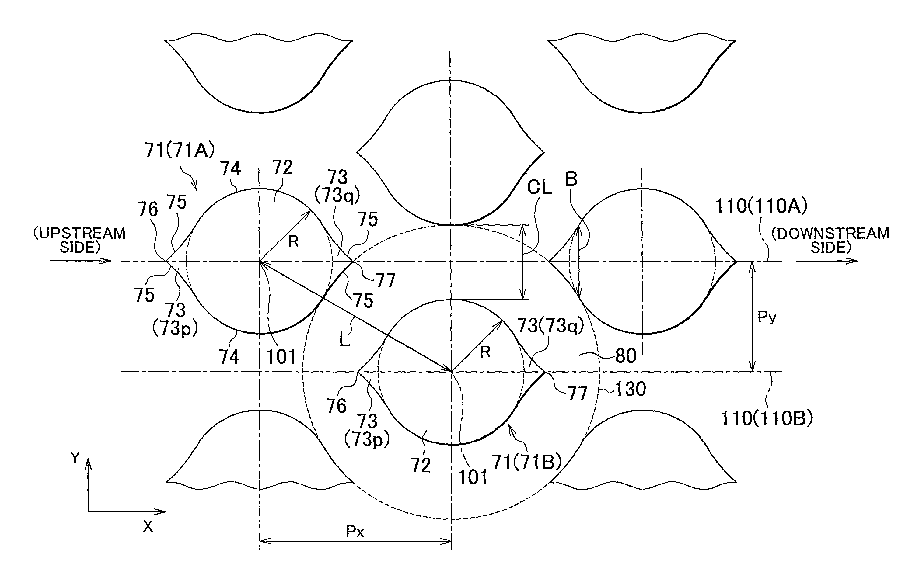
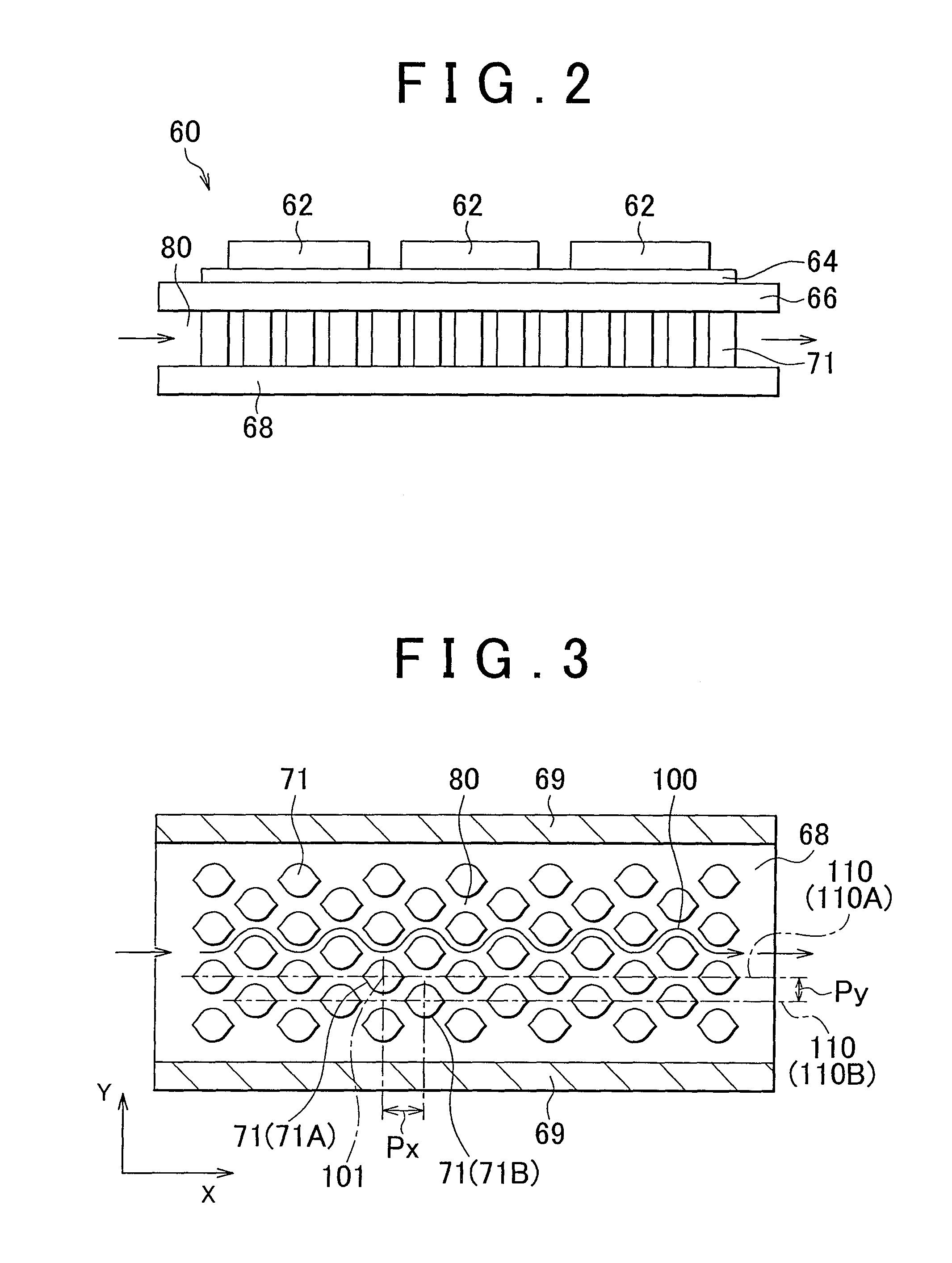
[0030]One embodiment of the invention will be described with reference to the drawings. In the drawings that will be referred to in the following description, the same reference numerals are assigned to the same or corresponding members or elements.

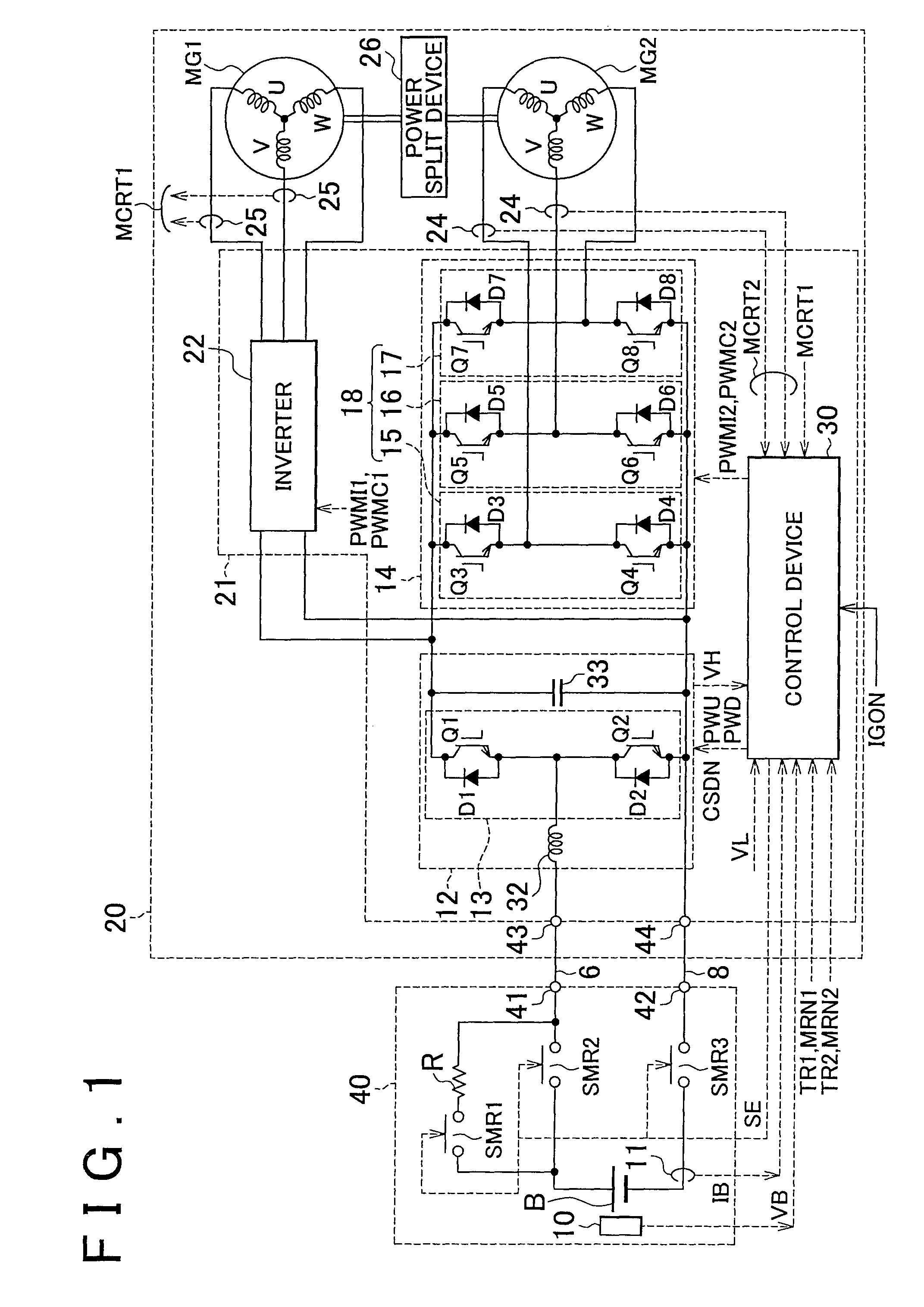
[0031]FIG. 1 is a circuit diagram showing the configuration of a system concerning motor-generator control of a hybrid vehicle. A cooling fin structure according to one embodiment of the invention is used in a cooler for a power control unit (PCT) installed on the hybrid vehicle. Referring to FIG. 1, the motor-generator control of the hybrid vehicle will be described.

[0032]The hybrid vehicle uses an internal combustion engine, such as a gasoline engine or a diesel engine, and motors to which electric power is supplied from a secondary battery capable of charging and discharging, as power sources.

[0033]The hybrid vehicle has a battery unit 40, a vehicular drive unit 20, and an engine (not shown). The vehicular drive unit 20 has motor-gener...


PUM


Abstract

A cooling fin structure used in a cooler for an electric device includes a plurality of pin fins (71) arranged in a zigzag form in a coolant passage (80). Each of the pin fins (71) has a circular portion (72) having a circular cross-section, and irregularly shaped portions (73) provided contiguously on the upstream and downstream sides of the circular portion (72) as viewed in a direction of flow of the coolant. The irregularly shaped portions (73) have an outer peripheral surface (75) that is formed along a circumference (130) having a center at a center point (101) of the circular portion (72) of a pin fin (71, 71B) that is located adjacent to the pin fin (71, 71A) having the irregularly shaped portions (73), in an oblique direction relative to the direction of flow of the coolant.

Description

BACKGROUND OF THE INVENTION[0001]1. Field of the Invention[0002]The invention generally relates to a cooling fin structure, and more particularly to a structure of cooling fins arranged in a zigzag form.[0003]2. Description of the Related Art[0004]A cooling fin device that arms at improving the cooling efficiency of cooling fins of a heat sink provided in an electronic device is disclosed in Japanese Patent Application Publication No. 2002-185175 (JP 2002-185175 A). In the cooling fin device disclosed in this publication, the cooling fins are discretely placed like pin-type fins, and have a streamline shape relative to the direction of flow of cooling water.[0005]Also, a cooling device for a semiconductor device as disclosed in Japanese Patent Application Publication No. 2003-324173 (JP 2003-324173 A) arms at efficiently dissipating heat while reducing a pressure loss in a coolant channel. In the cooling device for the semiconductor device as disclosed in this publication, protrudin...

Claims


Application Information

Patent Timeline
Patent Type & Authority Patents(United States)
IPC IPC(8): F28F13/06H01L23/473H05K7/20F28F1/40F28F3/02
CPCF28F1/40F28F3/022F28F13/06H01L23/473H05K7/2039H05K7/20254H05K7/20927H01L2924/0002H01L2924/00
Inventor KAWAURA, MASANORIMATSUI, HIROHITOYOSHIDA, TADAFUMI
Owner TOYOTA JIDOSHA KK
Why Eureka
Try Eureka