Electric-power conversion apparatus

Active Publication Date: 2020-07-23
MITSUBISHI ELECTRIC CORP
View PDF0 Cites 3 Cited by
  • Summary
  • Abstract
  • Description
  • Claims
  • Application Information

AI Technical Summary

Benefits of technology

[0012]In an electric-power conversion apparatus according to the present disclosure, a fuse portion is formed in an electrode wiring member; thus, because no expensive chip-type fuse is provided, the cost of the fuse portion can be reduced. Because a sealing resin member covers the fuse portion and a fuse resin member, the material of the melted fuse portion is prevented from scattering to the outside. Moreover, because the fuse portion and the fuse resin member can be shut down from the outer air, an arc discharge produced at a time of melting can be suppressed from making a combustion reaction proceed and smoke produced at a time of melting can be suppressed from leaking out to the outside. Covering the fuse portion with the fuse resin member makes it possible that the material of the melted fuse portion is suppressed from making contact with the sealing resin member and giving damage to the sealing resin member. Moreover, because the fuse resin member dedicated to the fuse portion is provided, it is made possible to select a resin member made of a material suitable for melting of the fuse portion. Accordingly, smoke emission, a burnout, and short-circuiting can

Problems solved by technology

In such an electric-power conversion apparatus, when while electric power is supplied from the battery, a short-circuit failure occurs in an electronic component such as an electric power semiconductor device or a smoothing capacitor included in a snubber circuit, an excessive short circuit current flows.
For example, when due to a malfunction of a gate driving circuit in an inverter control circuit, upper and lower arms of the inverter are short-circuited, an excessive current flows in the electric power semiconduc

Method used


Image

  • Electric-power conversion apparatus
  • Electric-power conversion apparatus
  • Electric-power conversion apparatus

Examples


embodiment 1

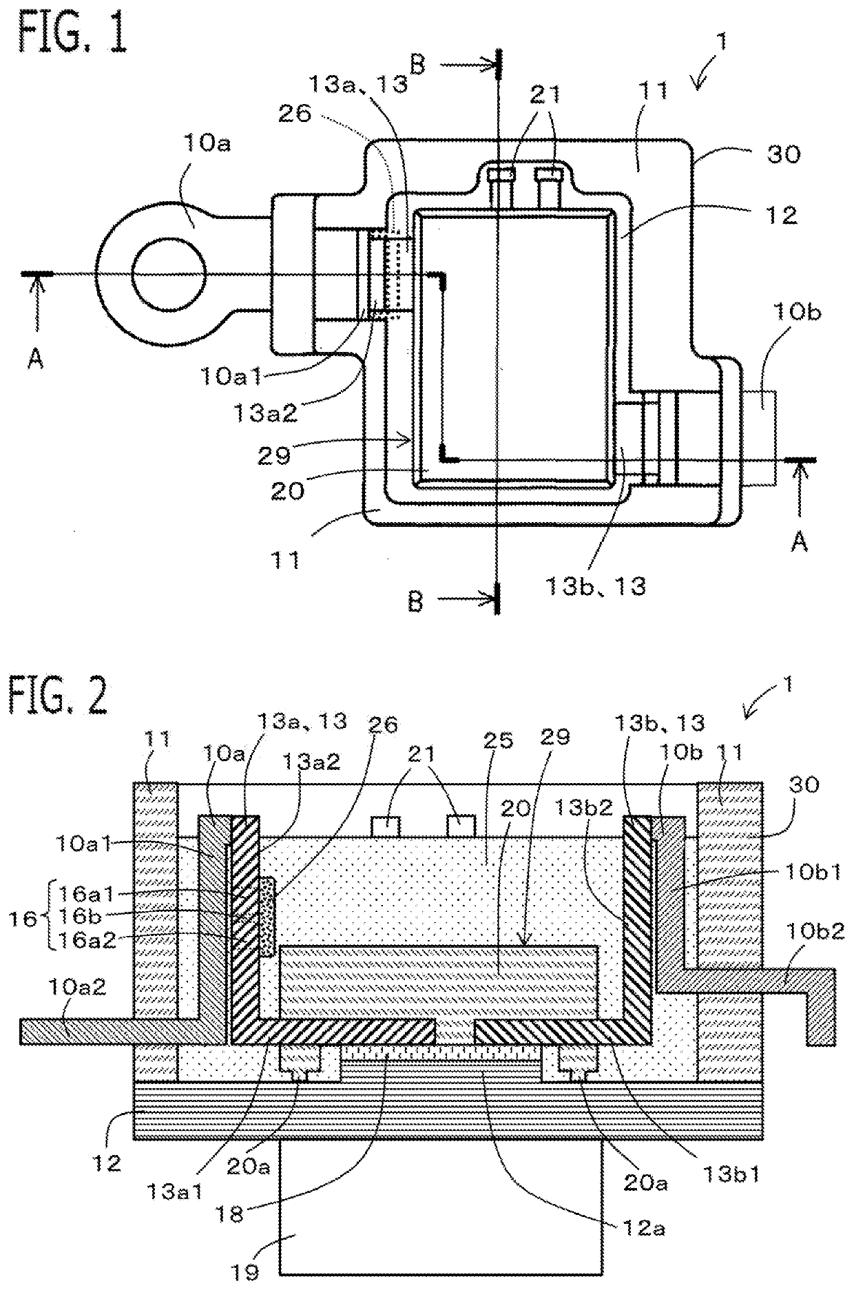
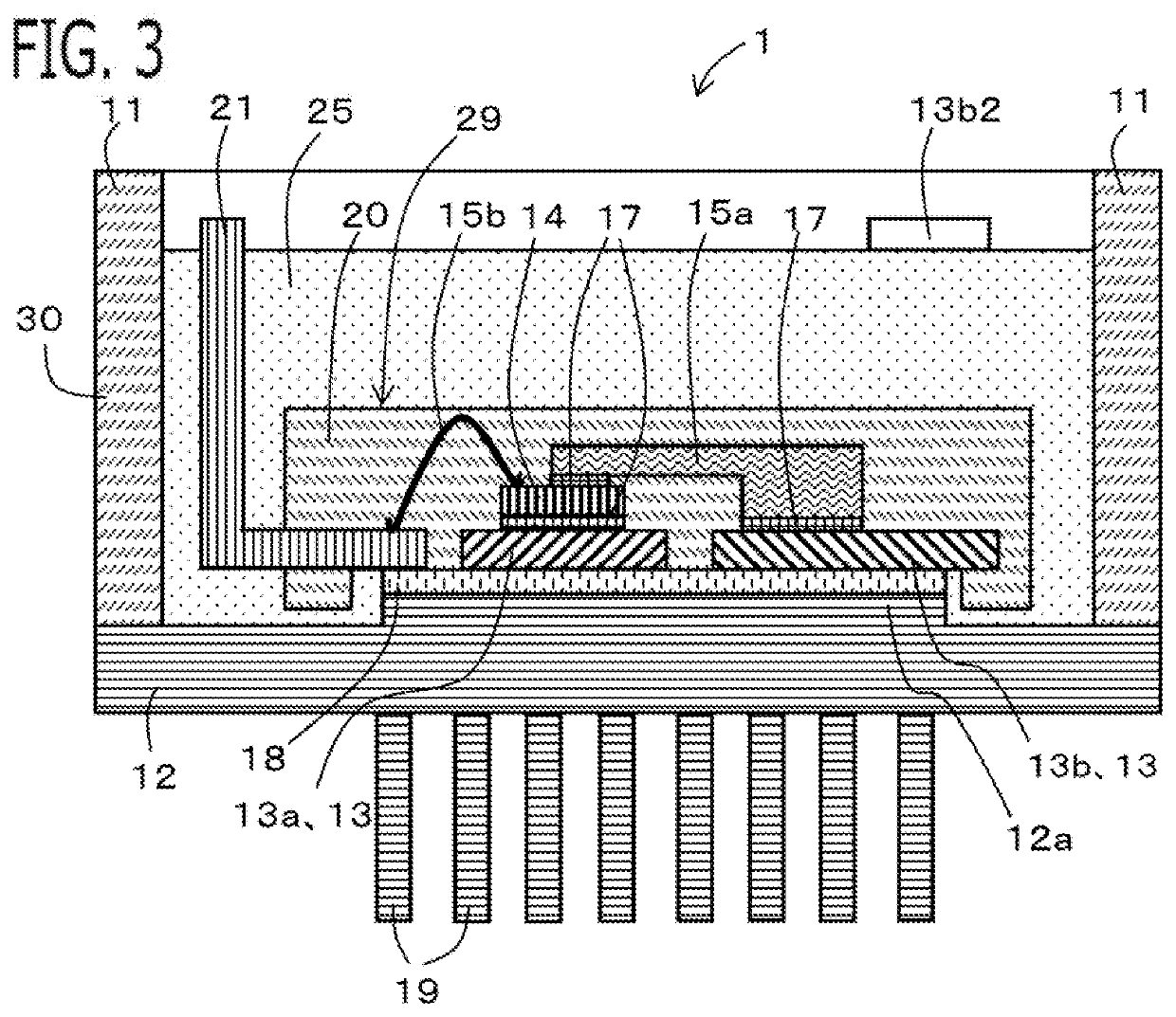
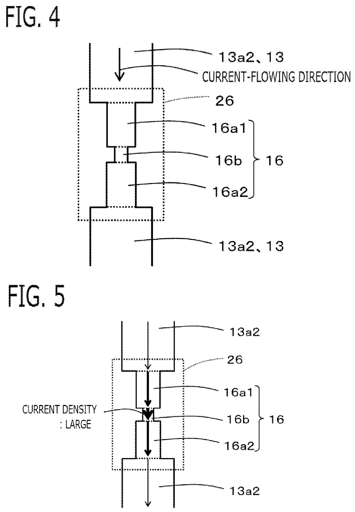
[0027]An electric-power conversion apparatus 1 according to Embodiment 1 will be explained with reference to drawings. FIG. 1 is a plan view of the electric-power conversion apparatus 1, when viewed from the opening side of a case 30; in order to explain the arrangement of respective components, a sealing resin member 25 is made transparent and is not illustrated. FIG. 2 is a cross-sectional view taken at the A-A cross-sectional position in FIG. 1; FIG. 3 is a cross-sectional view taken at the B-B cross-sectional position in FIG. 1. FIG. 4 is a plan view of a fuse portion 16 viewed from the front. Because each of the foregoing drawings is a schematic diagram, the respective dimensions of each of the members do not coincide with one another in the drawings.

[0028]The electric-power conversion apparatus1 includes an electric power semiconductor device 14, an electrode wiring member 13 connected with the main electrode of the electric power semiconductor device 14, the case 30, and the ...

embodiment 2

[0065]Next, an electric-power conversion apparatus 1 according to Embodiment 2 will be explained. The explanation for constituent portions that are the same as those in foregoing Embodiment 1 will be omitted. The basic configuration of the electric-power conversion apparatus 1 according to the present embodiment is similar to that of Embodiment 1; however, part of the configuration of an electrode wiring member 13 is different. FIG. 9 is a cross-sectional view of the electric-power conversion apparatus 1 according to the present embodiment, when taken at the A-A cross-sectional position in FIG. 1. FIG. 10 is a perspective view of a positive-polarity electrode lead frame 13a.

[0066]As is the case with Embodiment 1, a fuse portion 16 that functions as a fuse is formed in the electrode wiring member 13 (the positive-polarity electrode lead frame 13a). Unlike Embodiment 1, the electrode wiring member 13 (the positive-polarity electrode lead frame 13a) has a small-cross-sectional-area po...

embodiment 3

[0070]Next, an electric-power conversion apparatus 1 according to Embodiment 3 will be explained. The explanation for constituent portions that are the same as those in foregoing Embodiment 1 will be omitted. The basic configuration of the electric-power conversion apparatus 1 according to the present embodiment is similar to that of Embodiment 1; however, part of each of the configurations of a fuse resin member 26 and a positive-polarity external connection terminal 10a is different. FIG. 11 is a cross-sectional view of the electric-power conversion apparatus 1 according to the present embodiment, when taken at the A-A cross-sectional position in FIG. 1.

[0071]As is the case with Embodiment 1, the fuse resin member 26 is configured in such a way as to cover the surface at thickness-direction one side of the fuse portion 16 (in this example, the surface at the side opposite to the side of the positive-polarity external connection terminal 10a). However, unlike Embodiment 1, the port...


PUM


Abstract

There is provided an electric-power conversion apparatus in which smoke emission, a burnout, and short-circuiting can be suppressed even when a fuse portion is melted by an excessive current and in which it is made possible that heat generated in the fuse portion is less likely to be transferred to the electric power semiconductor device. The electric-power conversion apparatus includes a fuse portion formed in an electrode wiring member, a fuse resin member that covers the fuse portion, and a sealing resin member that seals an electric power semiconductor device and the fuse portion in a case. Along a current-flowing direction, the fuse portion includes an upstream-side first step portion whose cross-sectional area is smaller than that of the portion at the upstream side thereof, a second step portion whose cross-sectional area is smaller than that of the upstream-side first step portion, and a downstream-side first step portion whose cross-sectional area is larger than that of the second step portion but is smaller than that of the portion at the downstream side thereof.

Description

TECHNICAL FIELD[0001]The present disclosure relates to an electric-power conversion apparatus in which a resin member seals an electric power semiconductor device in a case.BACKGROUND ART[0002]In recent years, in the automobile industry, vehicles such as a hybrid automobile and an electric automobile, each of which utilizes a motor as a driving power source, have actively been developed. An inverter for driving the motor utilizes a battery as a power source so as to supply a high-voltage driving electric power to the motor. Moreover, a resin-sealing-type electric power semiconductor device is utilized in the inverter; thus, in the field of power electronics, the importance of an electric-power conversion apparatus, as a key device, is increasing more and more.[0003]The electric power semiconductor device utilized in the inverter and other constituent components are integrally sealed with resin. In such an electric-power conversion apparatus, when while electric power is supplied fro...

Claims


Application Information

Patent Timeline
IPC IPC(8): H01H85/10H01H85/18H01H85/38H01H85/02H01H85/165H02M7/48H01L23/62
CPCH01L23/62H01H85/10H01H85/0241H02M7/48H01H85/165H01H85/18H01H2085/0283H01H85/38H01H85/08H01L2224/32245H01L2224/48247H01L23/495H01L23/049H01L23/24H01L23/3135H01L23/36H01L23/49562H01L23/49524H01L2224/73265H01L2224/45144H01L2224/45147H01L2224/45124H01L2224/37144H01L2224/37139H01L2224/37147H01L2224/37124H01L24/45H01L24/37H01L2224/29101H01L2224/29339H01L24/29H01L2224/73221H01L24/73H01L24/40H01L24/32H01L2224/84801H01L2224/8485H01L24/84H01L2924/181H01L2924/00014H01L2924/014H01L2924/00H01L2924/00012
Inventor SHIRAKATA, YUJIFUJII, KENTAUENO, MASAHIROSHIMANO, TOMOAKI
Owner MITSUBISHI ELECTRIC CORP
Why Eureka
Try Eureka