
Process for the production of a detergent bar

a technology of detergent bars and detergent bars, applied in the direction of other chemical processes, soap solution manufacturing, manufacturing tools, etc., can solve the problems of die blockage, poor release of detergent bars from dies, and bar splitting in us

Inactive Publication Date: 2005-04-12
UNILEVER HOME & PERSONAL CARE USA DIV OF CONOPCO IN C
View PDF36 Cites 17 Cited by
  • Summary
  • Abstract
  • Description
  • Claims
  • Application Information

AI Technical Summary

Benefits of technology

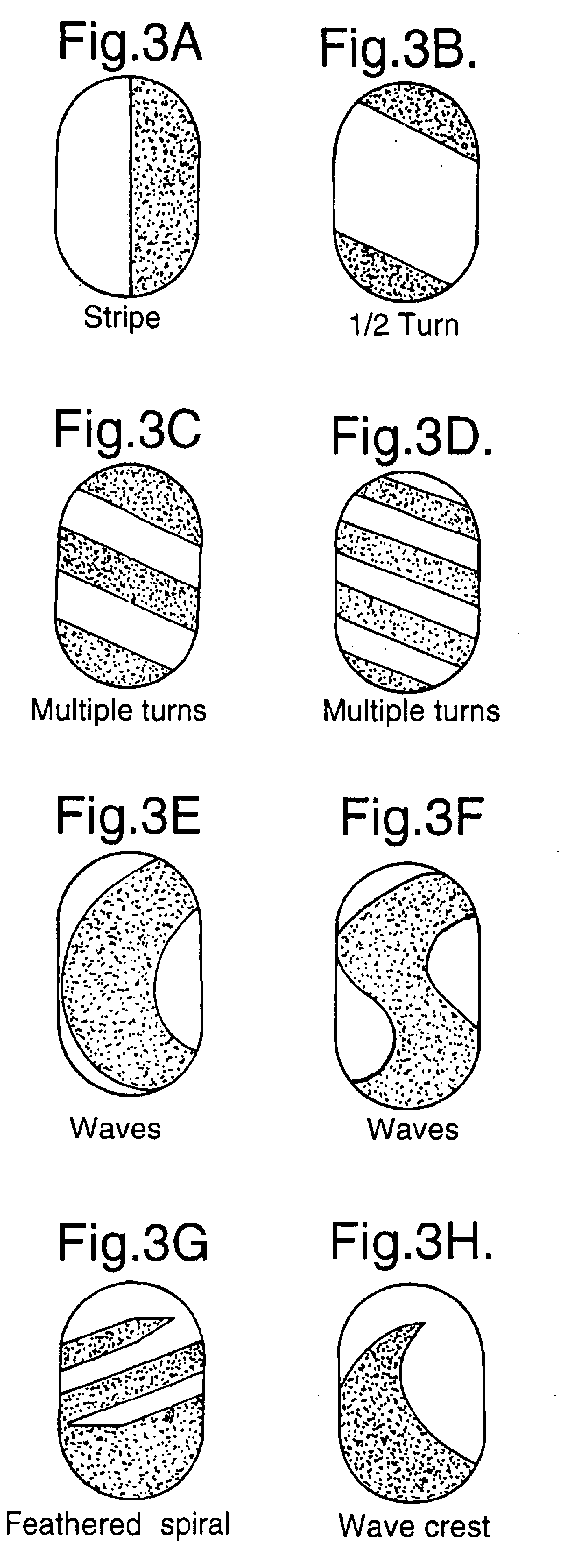
Although the process of the present invention is capable of producing a bar with distinct zones which are separated by a single longitudinal planar interface, as would be produced by the co-extrusion process, it is capable of producing much more complex zone patterns which cannot be produced by prior art processes.
Benefit agents may also include resins such as Knittex BE (Ciba-Geigy) or silicas such as Crosanaol NS (Crosfield), these benefit agents prevent pill formation on the fabric.

Problems solved by technology

If the two streams do not “weld” sufficiently well, this can result in cleavage planes within the bar, which can ultimately lead to bars splitting in use.
Moreover, the opportunity for varying the resultant decorative effects are clearly limited.
Other problems experienced with stamping processes, are poor release of the bars from the dies and die-blocking.
In die-blocking, small amounts of residual detergent left on dies builds up during continued use, which can result in visible imperfections on the bar surface.
Die-blocking can also lead to poor or even non-release of the bars from the die surface.
The stamping process can also lead to undesirable distortions of, for example, the striped or variegated pattern present in the billet as the material is stamped.
In addition, unlike with the manufacture of “homogeneous” bars, it is unlikely that the flash material generated in the stamping of a striped or variegated billet can be recycled back into the process, which adds considerably to the production costs.
However, the variety of bar forms that can be produced is very limited and the process can be expensive to operate.
Clearly this is awkward, time-consuming and only allows for a limited number of bar forms to be manufactured.
Certain detergent formulations are viscous liquids or semi-solids at commercially realistic temperatures and therefore do not lend themselves to casting.
Furthermore, in the casting process, the detergent melt tends to cool slowly and unevenly.
This can lead to unwanted structural orientations and segregation of ingredients.
A major problem with the casting process in general, is that detergent compositions in the moulds tend to shrink as they cool.
This is highly undesirable as the mould is intended to impart a distinctive shape to the bar and / or a logo of some kind.

Method used


Image

  • Process for the production of a detergent bar
  • Process for the production of a detergent bar
  • Process for the production of a detergent bar

Examples


Embodiment Construction

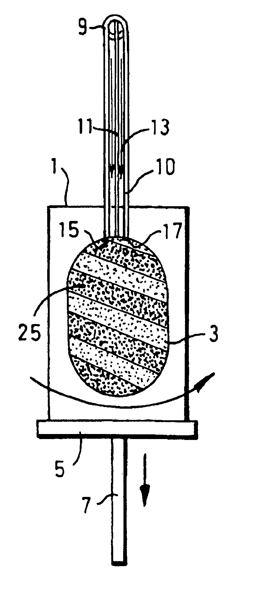
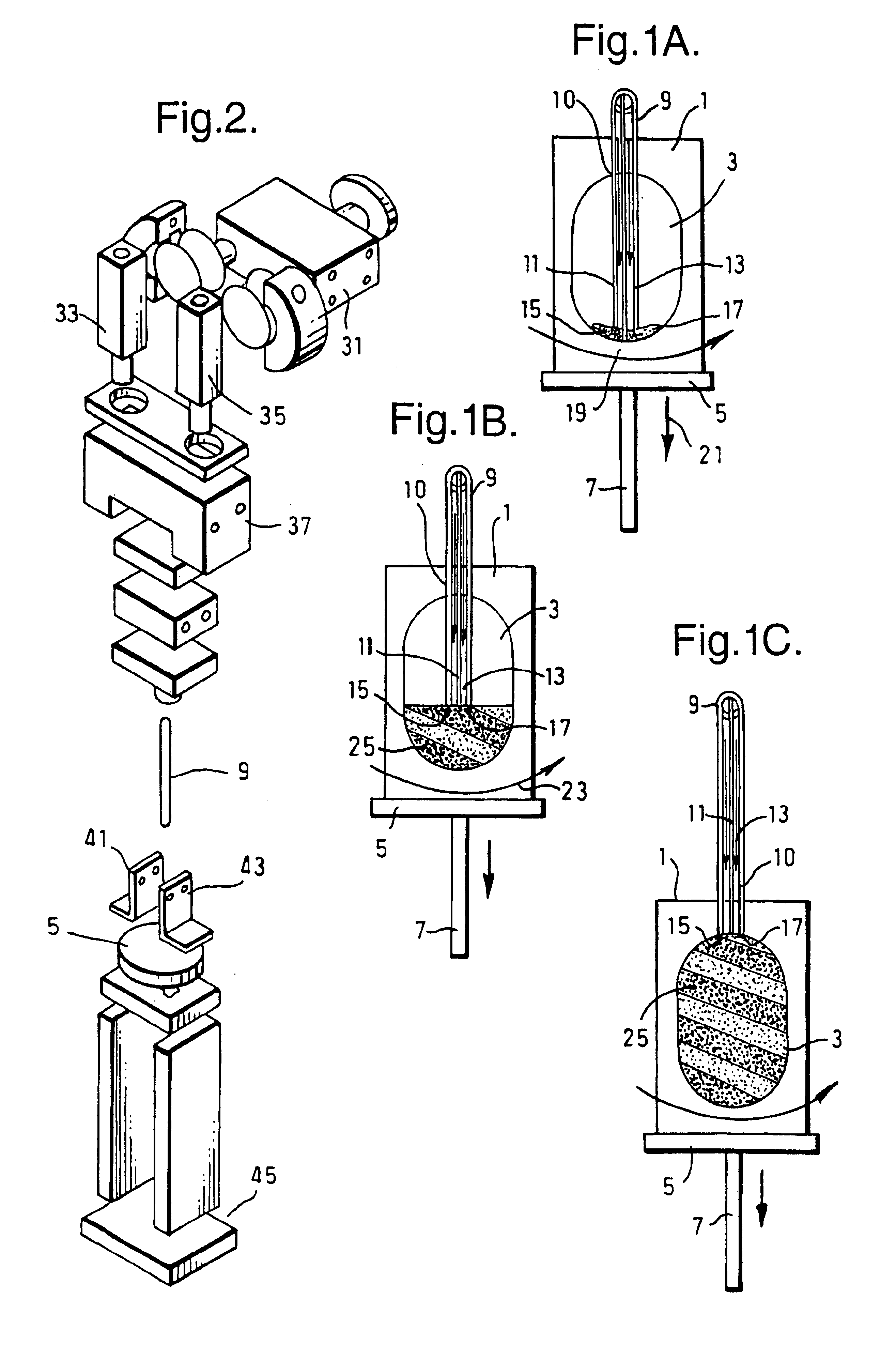
The present invention is based on use of an injection moulding process for the manufacture of detergent bars. Further details of suitable injection moulding techniques are given below. However, the minimum requirement for the process and apparatus according to the present invention is use of equipment comprising a mould and nozzle means having two or more orifices (e.g. nozzles) for separate injection of the respective components.

Preferably, the nozzle means is inserted inside the cavity through an opening in the mould, before injection commences. Then, it is withdrawn during injection. Withdrawal may be effected by moving the nozzle means relative to the mould or by moving the mould relative to the nozzle means, or both.

There are two ways in which the pattern of the two or more components may be varied during manufacture. The first is by controlling the relative motion between the nozzle means and the mould. The second is by varying the relative rates of injection of the different ...


PUM

PropertyMeasurementUnit
Percent by massaaaaaaaaaa
Viscosityaaaaaaaaaa
Compositionaaaaaaaaaa

Abstract

In an apparatus and process for manufacturing a detergent bar, the bar comprises a first distinct zone comprising a first component and at least a second distinct zone comprising a second component. In an injection step, the first and second components are injected into the mold cavity via nozzle means having a first orifice through which the first component is injected. The second component is injected through a second orifice of the nozzle means. The first and second components solidify in the cavity to form the bar. The interface between the zones may be non-planar and / or such that the zones cannot be separated by a unidirectional cut. The first and second zones may respectively comprise detergent and a benefit agent. The first and second zones may differ in texture.

Description

FIELD OF THE INVENTIONThe present invention relates to a process and apparatus for forming detergent bars and detergent bars formed by that process. The detergent bars can for example be of the personal wash and / or care type, laundry type (e.g. for the washing or other treatment of textile fabrics), or household care type (e.g. hand dishwash).BACKGROUND OF THE INVENTIONDetergent bars have conventionally been manufactured by one of two methods. The first of these is the so-called extrusion process in which a pre-formed composition comprising all components of the bar is typically plodded, i.e. extruded through an eye-plate, to form a continuous “rod”, and the continuous rod cut into smaller pieces of predetermined length, commonly referred to as “billets”. These billets are fed through a stamper, or alternatively, and especially in the production of low cost non-soap detergent (NSD) bars, are merely given an imprint on one or more surfaces. Such embossing or imprinting may be achieve...

Claims


Application Information

Patent Timeline
IPC IPC(8): C11D13/00C11D13/16C11D13/08
CPCC11D13/16C11D13/08Y10S425/803Y10S264/57Y10S425/032C11D17/0047B29C45/22C11D17/0052B29C45/34
Inventor BROWNE, MICHAEL ANDREWLLOYD, PAULMANI, SUDHIROVERTON, CHRISTINE ANNSTOCKER, FREDERICK EDMUND
Owner UNILEVER HOME & PERSONAL CARE USA DIV OF CONOPCO IN C
Learn More