Vapor barrier for use in the heat insulation of buildings

Inactive Publication Date: 2005-04-12
FRAUNHOFER GESELLSCHAFT ZUR FOERDERUNG DER ANGEWANDTEN FORSCHUNG EV
View PDF38 Cites 53 Cited by
  • Summary
  • Abstract
  • Description
  • Claims
  • Application Information

AI Technical Summary

Benefits of technology

[0007]According to the invention, a vapor barrier for use in the insulation of buildings is formed from a material which has a water vapor diffusion resistance dependent on an ambient humidity. At a relative humidity of an atmosphere surrounding the vapor barrier in the region of 30% to 50%,

Problems solved by technology

Moreover, the external appearance of the building is a significant factor here which also represents a limit to what can actually be done.
Similar difficulties also arise in subsequent full-rafter insulation on high-pitched roofs with a vapor-tight front covering, for example, roofing fabric on planking.
Thus tests carried out by the Fraunhofer Institut für Bauphysik in the case where vapor barriers were applied inside with a water vapor dif

Method used


Image

  • Vapor barrier for use in the heat insulation of buildings
  • Vapor barrier for use in the heat insulation of buildings
  • Vapor barrier for use in the heat insulation of buildings

Examples


Embodiment Construction

dditionally illustratively according to the invention, a polymer for the polymer coating is selected from the group consisting of polyvinyl alcohol, dispersed synthetic resin, methyl cellulose, linseed oil alkyd resin, bone glue and protein derivatives.

BRIEF DESCRIPTION OF THE DRAWINGS

[0023]The invention may best be understood by referring to the following detailed description and accompanying drawings which illustrate the invention. In the drawings:

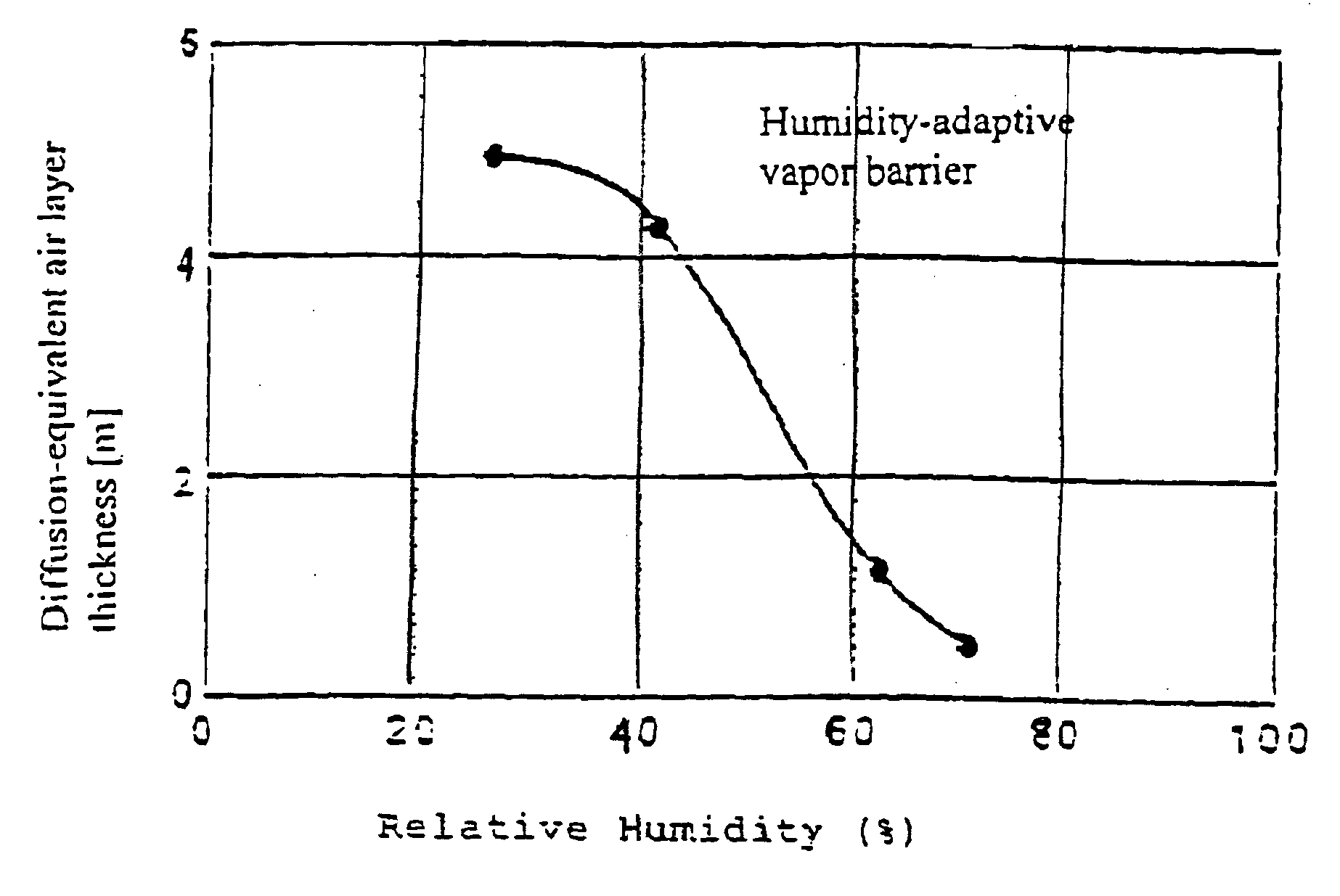
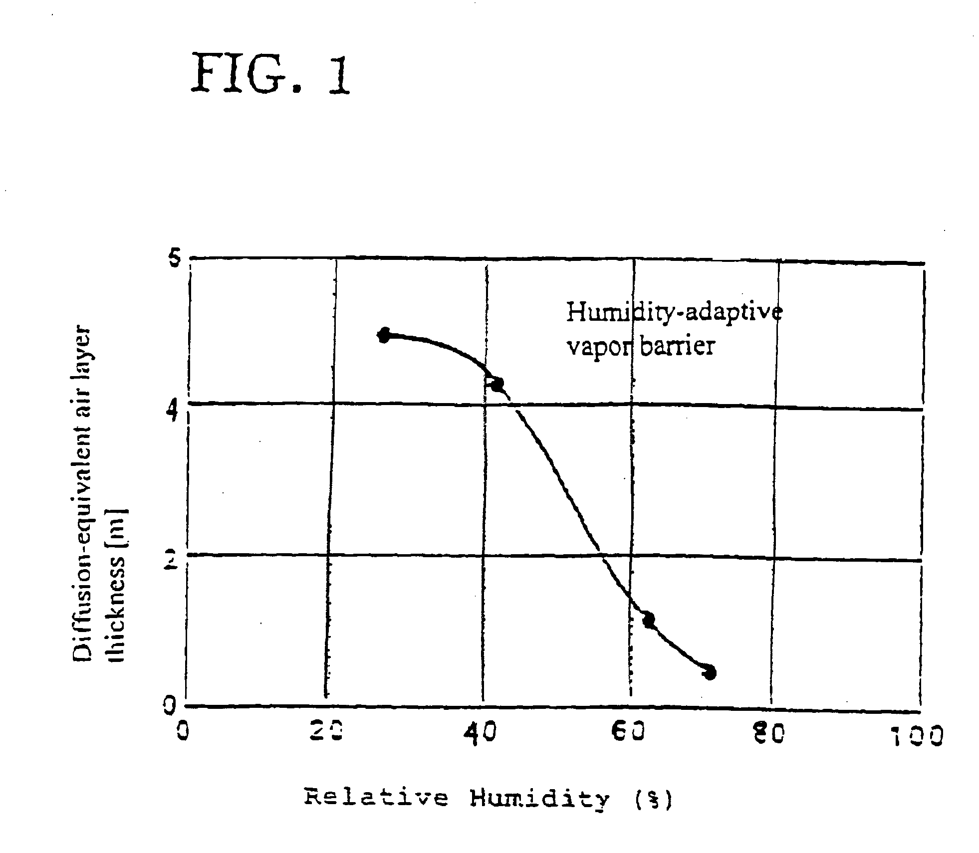
[0024]FIG. 1 illustrates the result for the diffusion-equivalent air layer thickness (sd value) of a vapor barrier constricted according to the invention as a function of the average relative humidity which prevailed during an experiment; and,

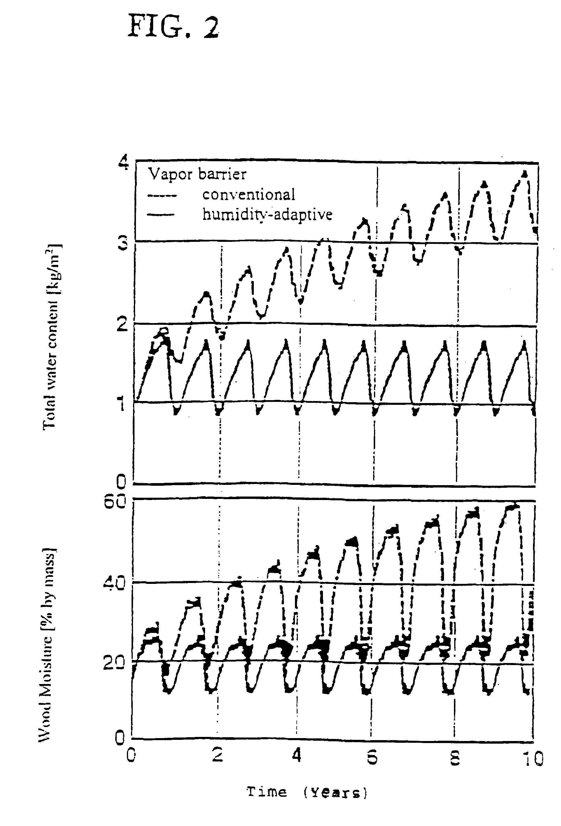
[0025]FIG. 2 illustrates comparative humidity characteristics of inter-rafter insulation using a prior art vapor barrier and using a humidity-adaptive vapor barrier constructed according to the present invention.

DESCRIPTION OF ILLUSTRATIVE EMBODIMENTS

[0026]The vapor barrier, which is applied facing ...


PUM

PropertyMeasurementUnit
Lengthaaaaaaaaaa
Lengthaaaaaaaaaa
Fractionaaaaaaaaaa

Abstract

The invention relates to a vapor barrier for use in the thermal insulation of buildings which can be used in particular, for thermal insulation procedures in new buildings or in the renovation of old buildings. The vapor barrier in accordance with the invention is thereby capable of achieving water vapor exchange under different ambient conditions. This is achieved by using a material which has a water vapor diffusion resistance which is dependent on the ambient humidity and which also has adequate tensile strength and tear resistance.

Description

CROSS-REFERENCES TO RELATED APPLICATIONS[0002]This application is a Divisional of U.S. patent application Ser. No. 09 / 521,125 filed Mar. 7, 2000, pending, which is a Continuation-in-part of U.S. patent application Ser. No. 08 / 945,146 filed Oct. 17, 1997, abandoned, which is the U.S. national phase of PCT / DE96 / 00705 filed Apr. 18, 1996, which claims priority to German patent application Ser. No. 195 14 420.1 filed Apr. 19, 1995BACKGROUND OF THE INVENTION[0003]The invention relates to a vapor barrier, which is arranged facing the room, for use in the thermal insulation of buildings, especially for thermal insulation procedures in new buildings and in the renovation of old buildings.[0004]In order to reduce the carbon dioxide emission which occurs as a result of heating buildings, thermal insulation procedures are carried out in the construction of new buildings and in the renovation of old buildings. For economic reasons, which constantly have to be considered by the owner of the buil...

Claims


Application Information

Patent Timeline
IPC IPC(8): E04B1/66E04D13/16B32B7/02E04B1/62E04C2/00E04D12/00
CPCB32B7/02B32B27/06E04D12/002E04D13/16E04B1/66B65H2301/36B65H2701/1313E04B1/625Y10T428/1341Y10S428/913Y10T428/1376Y10T442/695Y10T428/31993Y10T428/31772Y10T442/693Y10T428/31725Y10T428/31986Y10T428/31739Y10T442/674Y10T428/31779Y10T428/31783
Inventor KUNZEL, HARTWIGGROSSKINSKY, THEO
Owner FRAUNHOFER GESELLSCHAFT ZUR FOERDERUNG DER ANGEWANDTEN FORSCHUNG EV
Why Eureka
Try Eureka