Wheel support bearing assembly

a technology for supporting bearings and wheels, which is applied in the direction of brake systems, instruments, transportation and packaging, etc., can solve the problems of affecting the weight reduction of automotive vehicles, affecting the weight reduction of vehicles, and requiring a large number of processing steps

Inactive Publication Date: 2005-04-12
NTN CORP
View PDF19 Cites 23 Cited by
  • Summary
  • Abstract
  • Description
  • Claims
  • Application Information

AI Technical Summary

Benefits of technology

An object of the present invention is to provide an improved wheel support bearing assembly having a capability of detecting the number of revolutions of a wheel, substantially free from cable breakage occurring outside a vehicle body, and capable of being assembled compact, excellent in servicing of the detecting means for detection of the number of revolution of the wheel, and capable of contributing to reduction in weight and cost of the automotive vehicle.
With this control method, the control of the braking force can be performed correctly without being accompanied by an erroneous operation which would otherwise occur when the number of revolutions cannot be correctly recognized from the sensor output signal.

Problems solved by technology

Because of this, the electric cable is susceptible to breakage by the effect of stones hitting and / or frozen snow within a tire housing.
Also, in the case of a steering wheel, not only is it necessary for the electric cable to be twisted beforehand, but often times a relatively large number of processing steps is required.
The electric cable referred to above also requires a sheathing thereof and, therefore, reduction in weight of an automotive vehicle tends to be hampered and, in view of the large number of steps of fixing the electric cable, a high cost tends to be incurred.
Also, although the known wheel support bearing assembly of the type in which the sensor is built therein as shown in FIG. 35 can be assembled relatively compact, servicing of the rotation sensor 55 requires dismantling of the outer and inner races 51 and 52 of the wheel support bearing assembly, resulting in a problem that the servicing cannot be performed efficiently.
In addition, although the known wheel support bearing assembly shown in FIG. 35 is of the type wherein the rotation sensor is built therein, since the sensor portion 57 is partly exposed outside the bearing assembly, no sufficient reduction in size thereof is still achieved.
Yet, the known wheel support bearing assembly shown in FIG. 35 has a problem in that sealing of the hole 58 defined in the outer race 51 for receiving the sensor portion 57 is difficult to achieve, making it difficult to prevent any ingress of foreign matter.
However, even with the wireless interfacing system, any countermeasures against the external jamming radio waves are insufficient, and so is with illegal high power radio waves that are difficult to suppress.
As a result, there is no way of determining whether or not the wireless transmitted signal indicative of the number of revolution of the wheel has been affected by the external jamming radio waves and, hence, there is a high risk that the braking force cannot be properly controlled.

Method used


Image

  • Wheel support bearing assembly
  • Wheel support bearing assembly
  • Wheel support bearing assembly

Examples


fifth embodiment

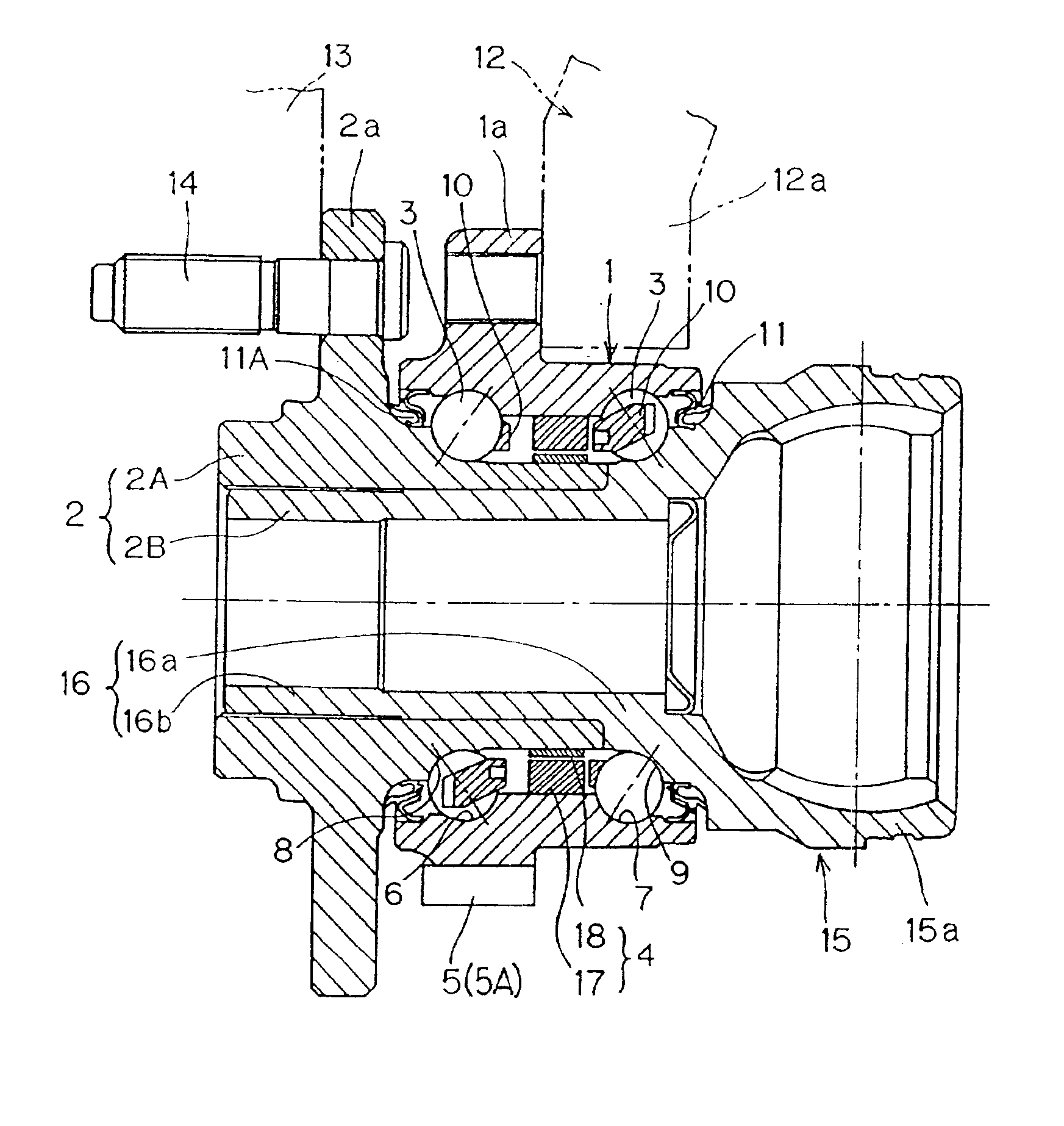
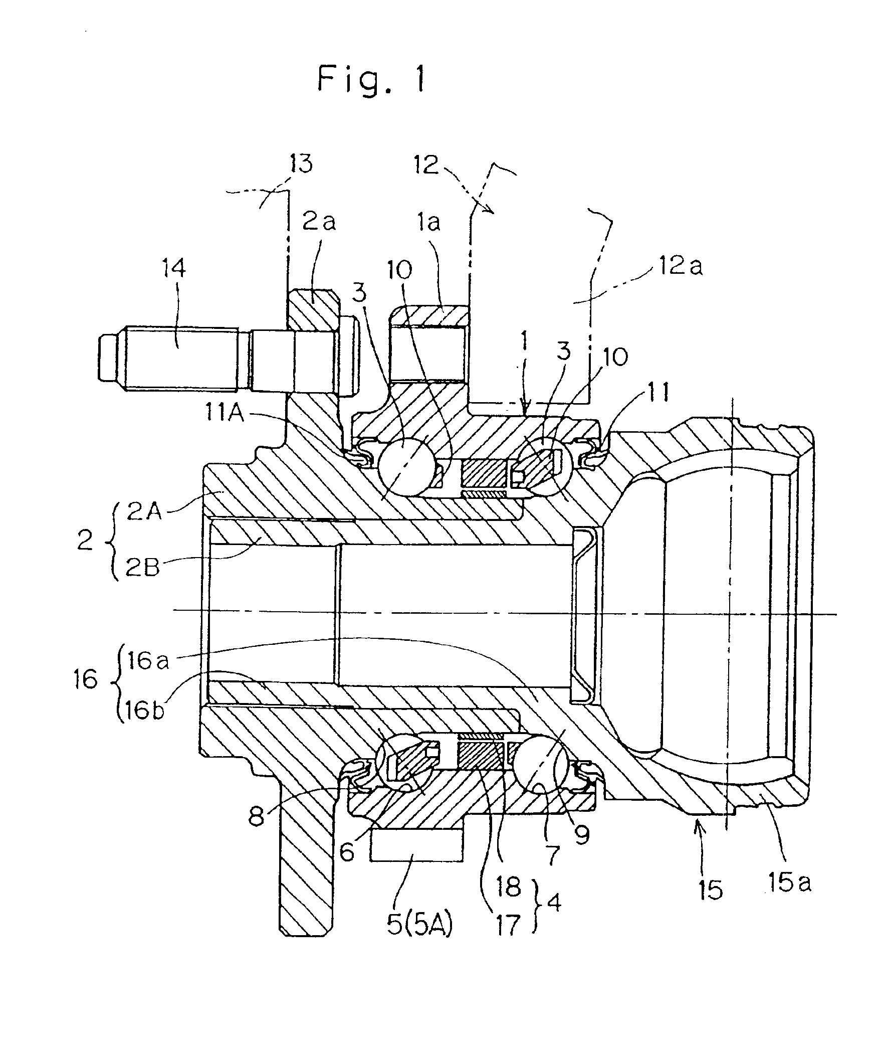
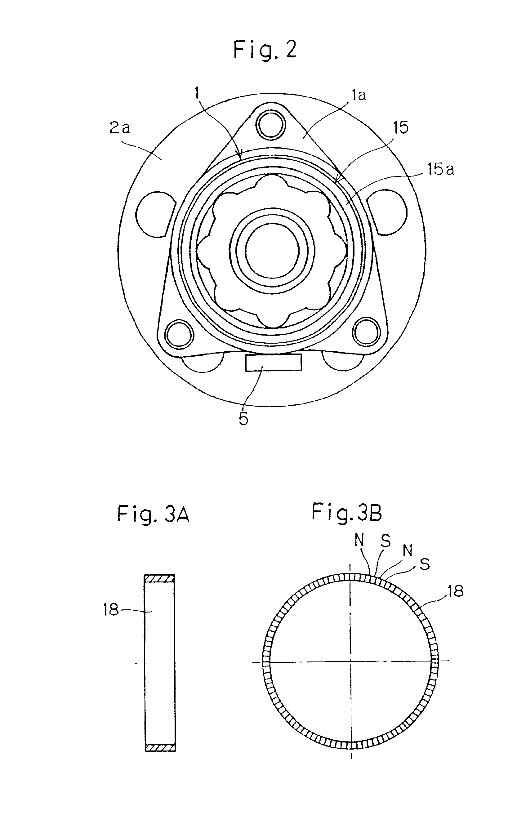
FIG. 11 illustrates the present invention. The wheel support bearing assembly shown therein is a wheel support bearing assembly of the inner race rotating type of a third generation and is used for rotatably supporting the drive axle.

According to this embodiment, in the wheel support bearing assembly of the third generation, the electric generator 4 of the thrust type which concurrently serves as the rotation sensor is incorporated in the sealing member 11, and the ring member 19 of the electric generator 4 is arranged axially of the annular transmitter 5A. The sealing member 11, the electric generator 4 and the transmitting means 5A are, unless otherwise specified, similar to those used in the second embodiment shown in and described with reference to FIG. 7. Briefly speaking, the multi-pole magnet 18 is fixed on the inner member 2 together with the first sealing member 31. The coil / magnetic element combination 17 is fixed on the outer member 1 through the fitting ring 49 to which ...


PUM


Abstract

A wheel support bearing assembly for rotatably supporting a wheel 13 relative to a vehicle body structure 12 includes outer and inner members 1 and 2 with dual rows of rolling elements 3 interposed therebetween. An electric generator 4 for generating an electric power as one of the inner and outer members 1 and 2 rotates relative to the other of the inner and outer members 1 and 2 is utilized. The electric generator 4 includes a coil / magnetic element combination 17, including a ring member accommodating a coil therein, and a multi-pole magnet 18. A signal outputted from the electric generator 4 and indicative of the number of revolutions of the wheel 13 is transmitted wireless by a transmitter 5. This transmitter 5 may be an annular transmitter.

Description

BACKGROUND OF THE INVENTION1. Field of the InventionThe present invention relates to a wheel support bearing assembly for use in an automotive vehicle and, more particularly, to the wheel support bearing assembly including an electric generator that serves as a means for detecting the number of revolution for an anti-skid braking mechanism.2. Description of the Prior ArtAn anti-skid brake device (ABS), also referred to as an anti-lock brake device, is known as used for detecting the incipiency of a tire lock occurring on a low frictional road surface or at the time of a panic stricken braking so that braking can be relieved to secure a tire grip to thereby stabilize the steerability. A sensor for detecting the number of revolutions of a wheel for detecting the incipiency of the tire being locked is provided in a wheel support bearing assembly. This sensor generally includes a pulsar ring provided at an end portion or the like of a raceway in a bearing outside, and a sensor portion p...

Claims


Application Information

Patent Timeline
Patent Type & Authority Patents(United States)
IPC IPC(8): B60T8/171B60T8/32B60T8/17G01P3/42G01P3/44
CPCB60T8/171B60T8/329F16C41/004F16C41/007F16C41/008G01P3/443F16C33/7879F16C33/7886F16C33/7896F16C19/184F16C2326/02
Inventor OKADA, KOICHIOHTSUKI, HISASHITORII, AKIRANORIMATSU, TAKAYUKIOHBA, HIROAKITAKAHASHI, TORUMIZUTANI, MASATOSHI
Owner NTN CORP
Why Eureka
Try Eureka