
Vertical weather profile display system and method

a technology of vertical weather and display system, applied in the direction of ict adaptation, reradiation, instruments, etc., can solve the problems of increasing pilot workload, conventional radar systems may only produce the desired results in a limited environment,

Active Publication Date: 2005-04-12
ROCKWELL COLLINS INC
View PDF33 Cites 136 Cited by
  • Summary
  • Abstract
  • Description
  • Claims
  • Application Information

AI Technical Summary

Problems solved by technology

Conventional radar systems may produce the desired results only in a limited environment.
However, knowledge by the pilot must be acquired, and further, an increase in pilot workload is also necessitated.

Method used


Image

  • Vertical weather profile display system and method
  • Vertical weather profile display system and method
  • Vertical weather profile display system and method

Examples


Embodiment Construction

Before describing in detail the particular improved system and method, it should be observed that the invention includes, but is not limited to a novel structural combination of conventional data / signal processing components and circuits, and not in the particular detailed configurations thereof. Accordingly, the structure, methods, functions, control and arrangement of conventional components and circuits have, for the most part, been illustrated in the drawings by readily understandable block representations and schematic diagrams, in order not to obscure the disclosure with structural details which will be readily apparent to those skilled in the art, having the benefit of the description herein. Further, the invention is not limited to the particular embodiments depicted in the exemplary diagrams, but should be construed in accordance with the language in the claims.

In conventional aircraft systems, air carriers wish to detect threatening weather which may be a threat to the air...


PUM


Abstract

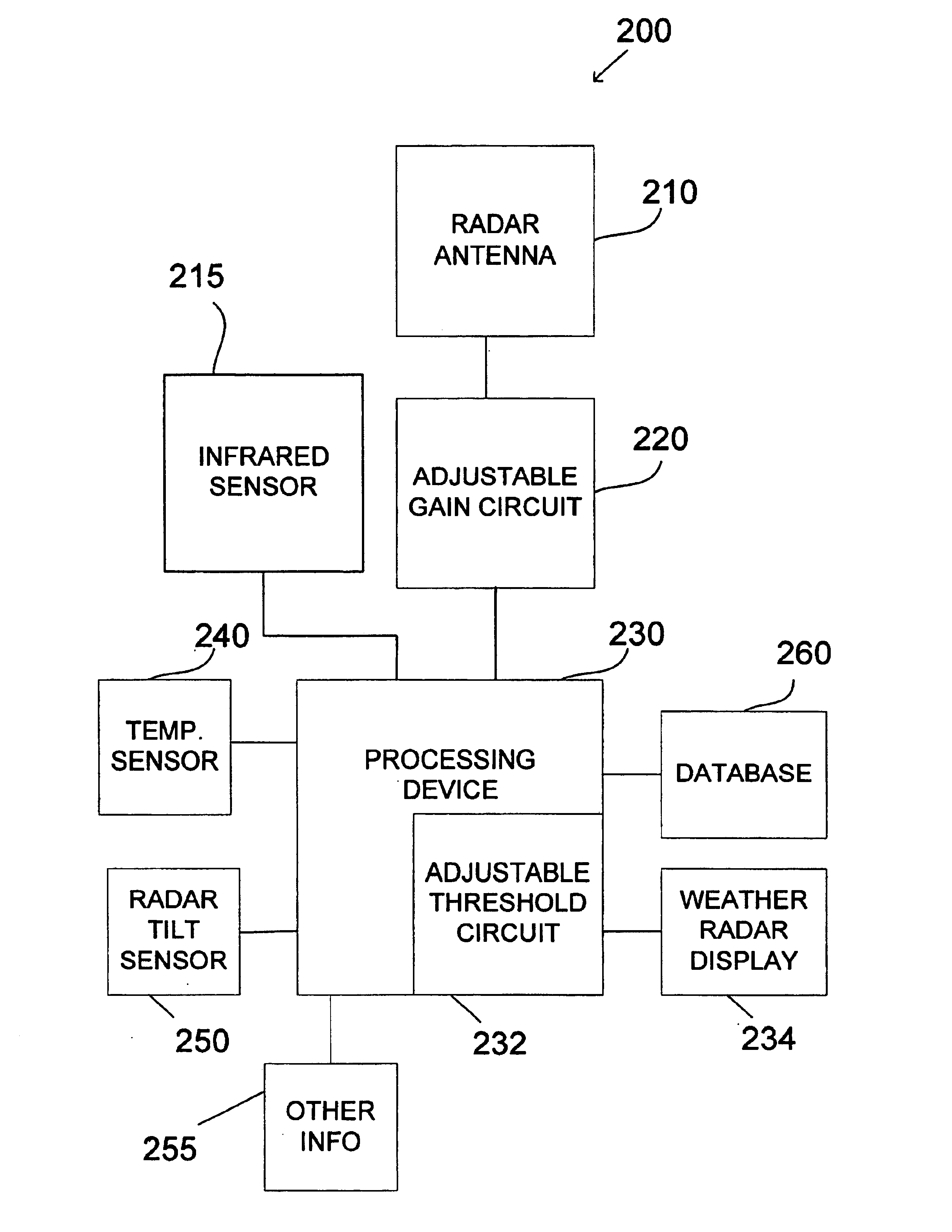
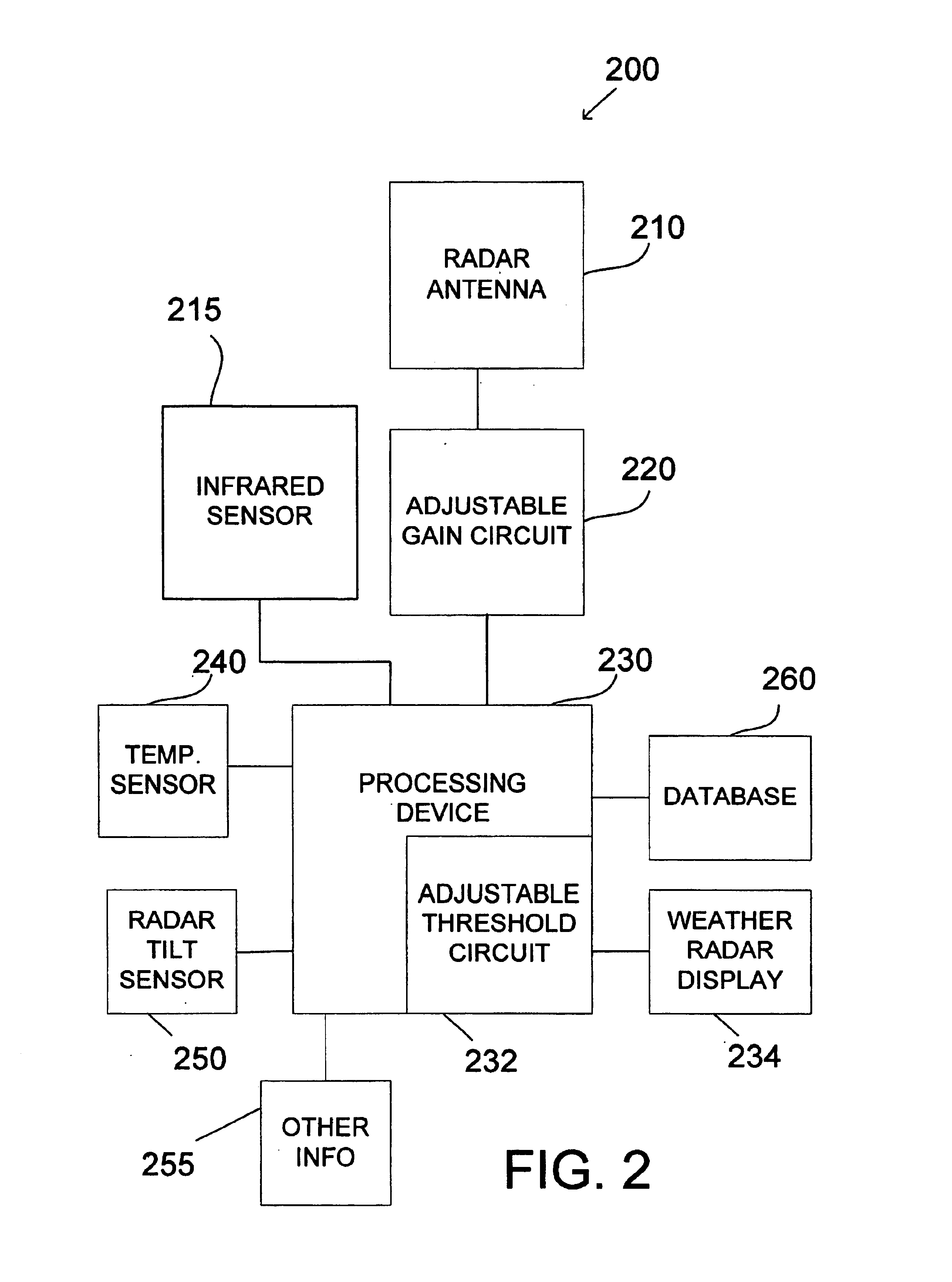
An aircraft weather radar system is disclosed. The system comprises a radar antenna, aircraft sensors, and a database. The system also comprises a processing device receiving information from the radar antenna and from the aircraft sensors and able to retrieve information from the database. Further, the system comprises a cockpit display coupled to the processing device. The processing device is programmed to estimate storm system characteristics based on the received information from the aircraft sensors and the database and to display the storm system characteristics on a vertical weather profile display using a graphical representation.

Description

BACKGROUNDConventionally, pilots use weather radar to detect and then avoid hazardous weather. Conventional radar systems may produce the desired results only in a limited environment. Typically, airborne threshold systems are traceable to ground-based weather radar thresholds for wet precipitation generated from convective weather. As such, conventional aircraft radar systems are used to detect the amount of water in an air mass. Analysis and / or estimation of the characteristics of a weather cell or storm cell due to the precipitation or other weather conditions is typically not done.Conventionally, radar thresholds map radar return strength to a display with color representing rain rate or alternatively a weather threat assessment level. Conventionally, the threat level has been previously described as primarily a function of radar reflectivity and a weaker function of temperature, altitude, and latitude or other information. Because of the ability of aircraft to circumnavigate st...

Claims


Application Information

Patent Timeline
Patent Type & Authority Patents(United States)
IPC IPC(8): G01S13/95G01S13/00G01S7/18G01S7/04G01S13/86
CPCG01S7/18G01S13/953G01S13/86Y02A90/10
Inventor BULL, IAN J.PARAMORE, STEVEWOODELL, DANIEL L.
Owner ROCKWELL COLLINS INC
Learn More