Methods, apparatuses and systems facilitating aggregation of physical links into logical link

a technology of physical link and logical link, applied in the field of telecommunications systems, can solve the problems of limiting the allowable difference in link speed between bonded links, requiring the use of expensive optical fiber and optical network equipment, and unattractive ds3 links for many enterprise customers, so as to improve the efficiency of data transfer, reduce the delay, and improve the effect of reliability

Inactive Publication Date: 2005-04-12
KLAMATH NETWORKS
View PDF11 Cites 64 Cited by
  • Summary
  • Abstract
  • Description
  • Claims
  • Application Information

AI Technical Summary

Benefits of technology

The present invention provides methods, apparatuses and systems facilitating the aggregation or bonding of physical communications links into higher-bandwidth logical links. The link bonding and encapsulation protocol scheme of the present invention allows for an embodiment that optimizes the efficiency of data transfer across the physical links, while still allowing for desired Quality of Service (QoS) levels to high-priority traffic, such as voice data, with low delay requirements. Embodiments of the present invention allow a variety of service types to be transported transparently over bonded physical links. According to on

Problems solved by technology

DS3 links, however, are unattractive to many enterprise customers since electrical DS3 solutions are capable of supporting access links of only about 900 feet in length, therefore mandating use of expensive optical fiber and optical network equipment for any access link spanning a significant distance.
For IMA, the third requirement ends up being the most taxing on the solution, because an ATM cell is a fixed size packet, and therefore does not allow for the simple addition of a sequence number to every c

Method used


Image

  • Methods, apparatuses and systems facilitating aggregation of physical links into logical link
  • Methods, apparatuses and systems facilitating aggregation of physical links into logical link
  • Methods, apparatuses and systems facilitating aggregation of physical links into logical link

Examples


Embodiment Construction

I. Operating Environment

A. Functional Overview

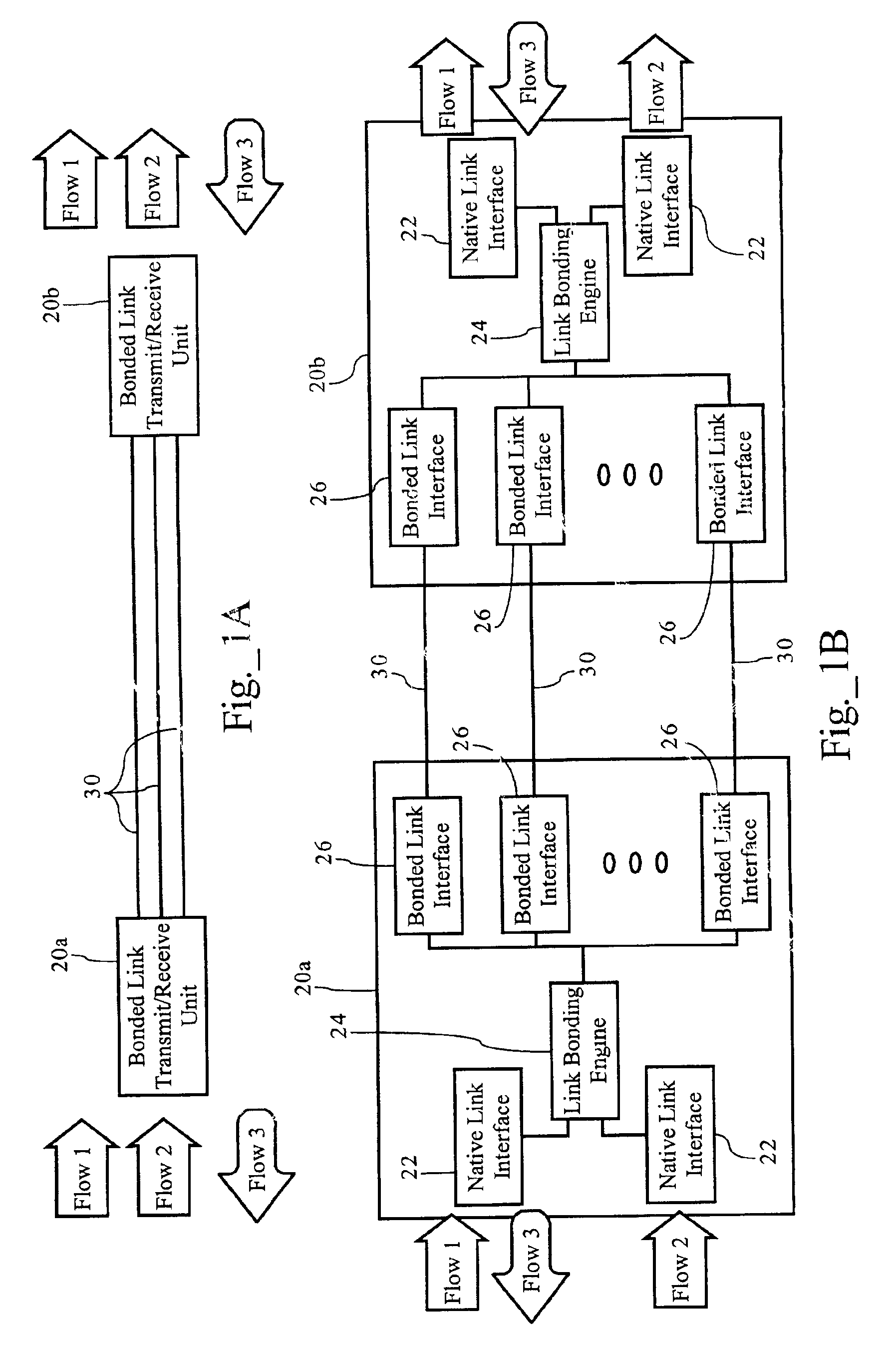
FIG. 1A illustrates operation of the link aggregation functionality according to one embodiment of the present invention. As FIG. 1 illustrates, a plurality of physical links 30 operably connect a first bonded link transmit / receive unit 20a to a second bonded link transmit / receive unit 20b. As discussed more fully below, bonded link transmit / receive unit 20a, in the transmit direction (e.g., flows 1 and 2), processes native flows and transmits them across one or more bonded links 30 to a second bonded link transmit / receive unit 20b, which reassembles the native flows for further transmission. As FIG. 1A illustrates, bonded link transmit / receive units 20a and 20b also operate in the reverse direction. In addition, as FIG. 1A illustrates, the link aggregation system transports native flows transparently across bonded links 30. In one embodiment, physical link 30 is an xDSL link, such as a VDSL link. Of course, one skilled in the art will r...


PUM


Abstract

Methods, apparatuses and systems facilitating the aggregation or bonding of physical communications links into higher-bandwidth logical links. A novel link bonding and encapsulation protocol scheme that optimizes the efficiency of data transfer across the physical links, while still allowing for desired Quality of Service (QoS) levels to high-priority traffic, such as voice data, with low delay requirements. Data streams are divided and concurrently transported over multiple physical links that are aggregated or bonded together to form one logical link. At the receive end, the original cell streams are recovered from the bonded logical links. In one embodiment, the physical links are xDSL links transmitting and receiving signals via conventional copper twisted-pair cabling. In one embodiment, the present invention allows telecommunications service providers to leverage their investments in existing twisted pair connection technologies to deliver high-bandwidth services to customers in a fast and cost-efficient manner.

Description

FIELD OF THE INVENTIONThe present invention relates to telecommunications systems and, more particularly, to methods, apparatuses and systems enabling a link bonding scheme facilitating the aggregation of physical links into higher-bandwidth, logical links.BACKGROUND OF THE INVENTIONDS1 links, providing an access capacity of 1.5 Megabits per second (Mbps), dominate the existing access infrastructure. The next logical bandwidth step in the PDH / SDH hierarchy is DS3, which delivers an access capacity of roughly 45 Mbps. DS3 links, however, are unattractive to many enterprise customers since electrical DS3 solutions are capable of supporting access links of only about 900 feet in length, therefore mandating use of expensive optical fiber and optical network equipment for any access link spanning a significant distance. Accordingly, customers requiring more bandwidth than a DS1 link, found themselves reluctant to incur the expense associated with DS3 links. Therefore, it quickly became a...

Claims


Application Information

Patent Timeline
IPC IPC(8): H04M11/06H04L12/56
CPCH04L45/00H04M11/062H04L45/245Y02B60/33Y02D30/50
Inventor PEDERSEN, SOREN BOSHILSHTUT, RADIMIRTHOM, DANNYSOLTANI, SINAMAY, LAUREN TREVOR
Owner KLAMATH NETWORKS
Why Eureka
Try Eureka