Tile-based digital watermarking techniques

a technology of digital watermarking and tiles, applied in image data processing details, special data processing applications, record information storage, etc., can solve problems such as difficult follow-up of work

Inactive Publication Date: 2005-04-12
DIGIMARC CORP (FORMERLY DMRC CORP)
View PDF32 Cites 235 Cited by
  • Summary
  • Abstract
  • Description
  • Claims
  • Application Information

AI Technical Summary

Problems solved by technology

The work is somewhat difficult to follow but apparently results in a simple yes/no determin

Method used


Image

  • Tile-based digital watermarking techniques
  • Tile-based digital watermarking techniques
  • Tile-based digital watermarking techniques

Examples


first embodiment

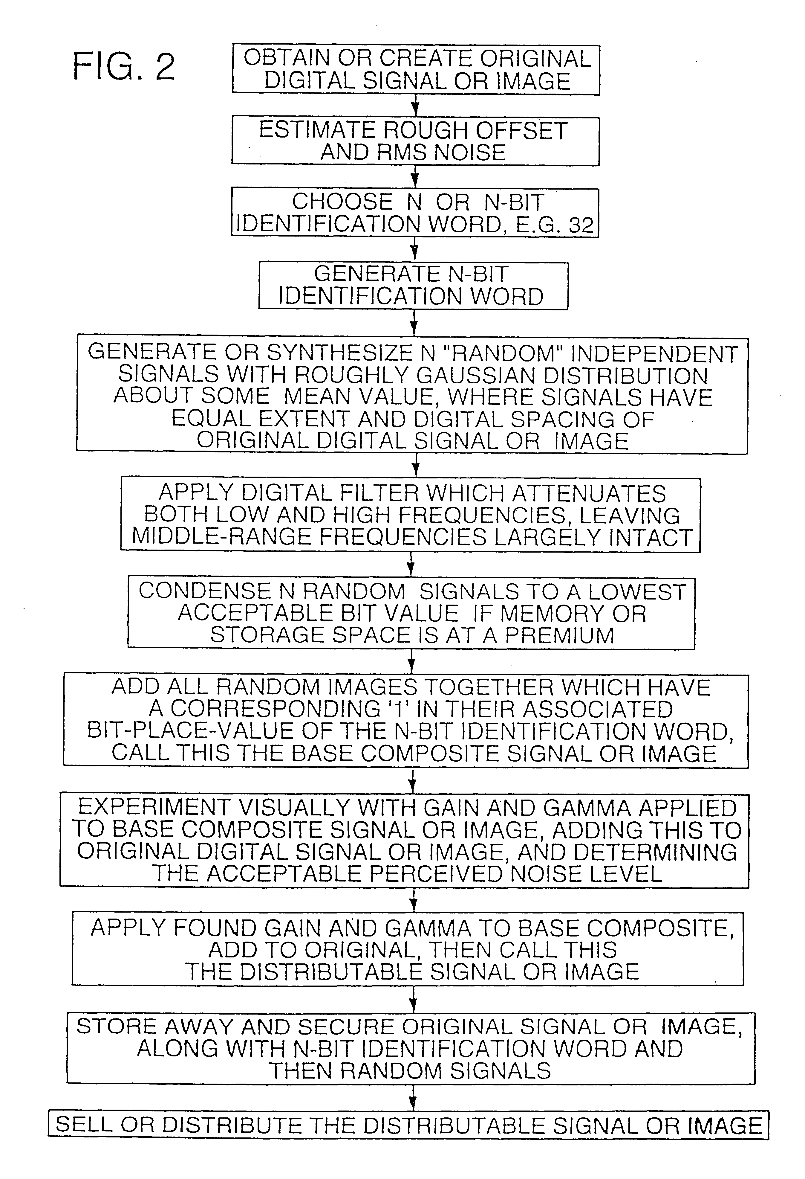
The detailed methodology of this first embodiment begins by stating that the N-bit identification word is encoded onto the original signal by having each of the m bit values multiply their corresponding individual embedded code signals, the resultant being accumulated in the composite signal, the fully summed composite signal then being attenuated down to the acceptable perceived noise amplitude, and the resultant composite signal added to the original to become the distributable signal.

The original signal, the N-bit identification word, and all N individual embedded code signals are then stored away in a secured place. A suspect signal is then found. This signal may have undergone multiple copies, compressions and decompressions, resamplings onto different spaced digital signals, transfers from digital to analog back to digital media, or any combination of these items. IF the signal still appears similar to the original, i.e. its innate quality is not thoroughly destroyed by all of...

specific example

Imagine that we have taken a valuable picture of two heads of state at a cocktail party, pictures which are sure to earn some reasonable fee in the commercial market. We desire to sell this picture and ensure that it is not used in an unauthorized or uncompensated manner. This and the following steps are summarized in FIG. 2.

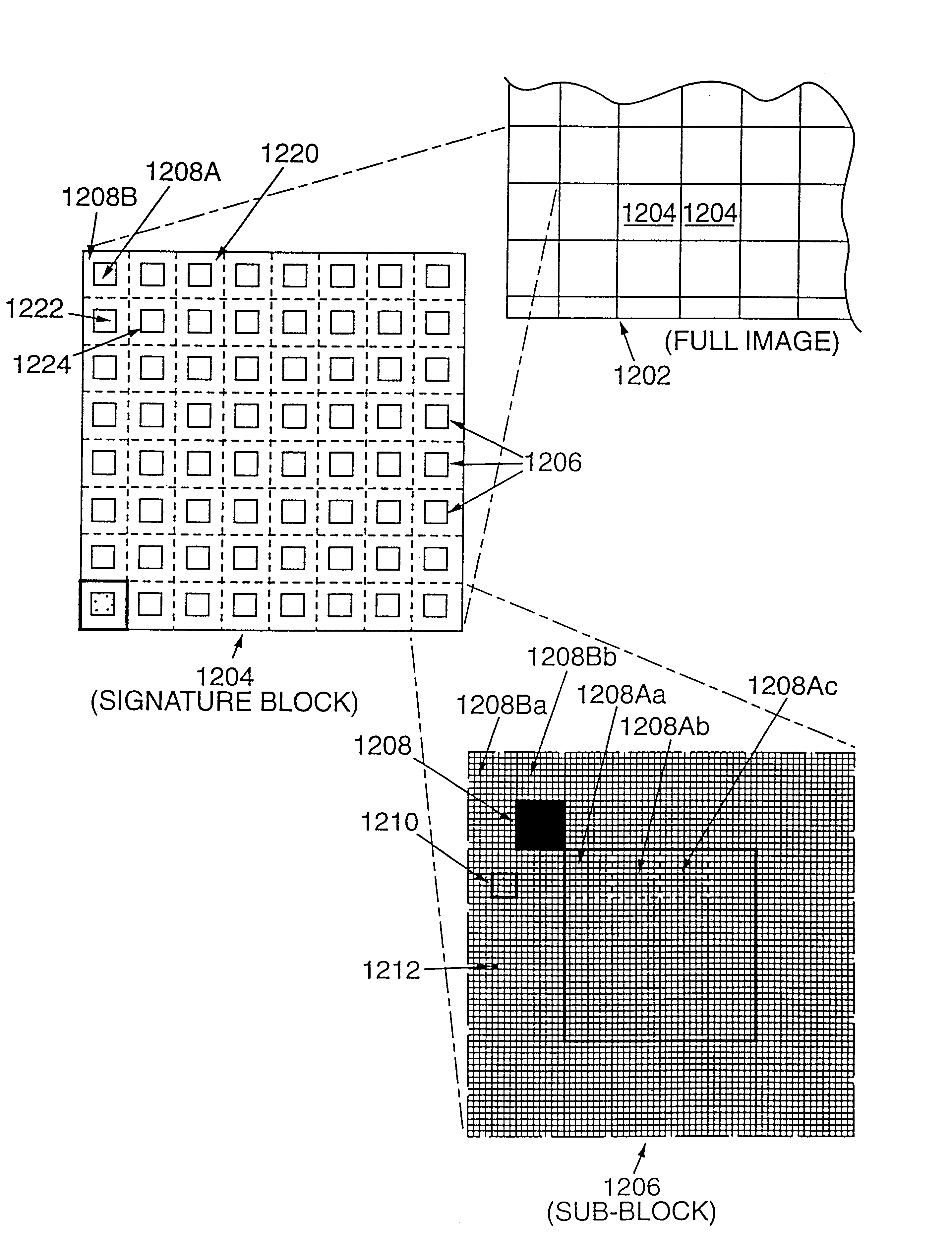
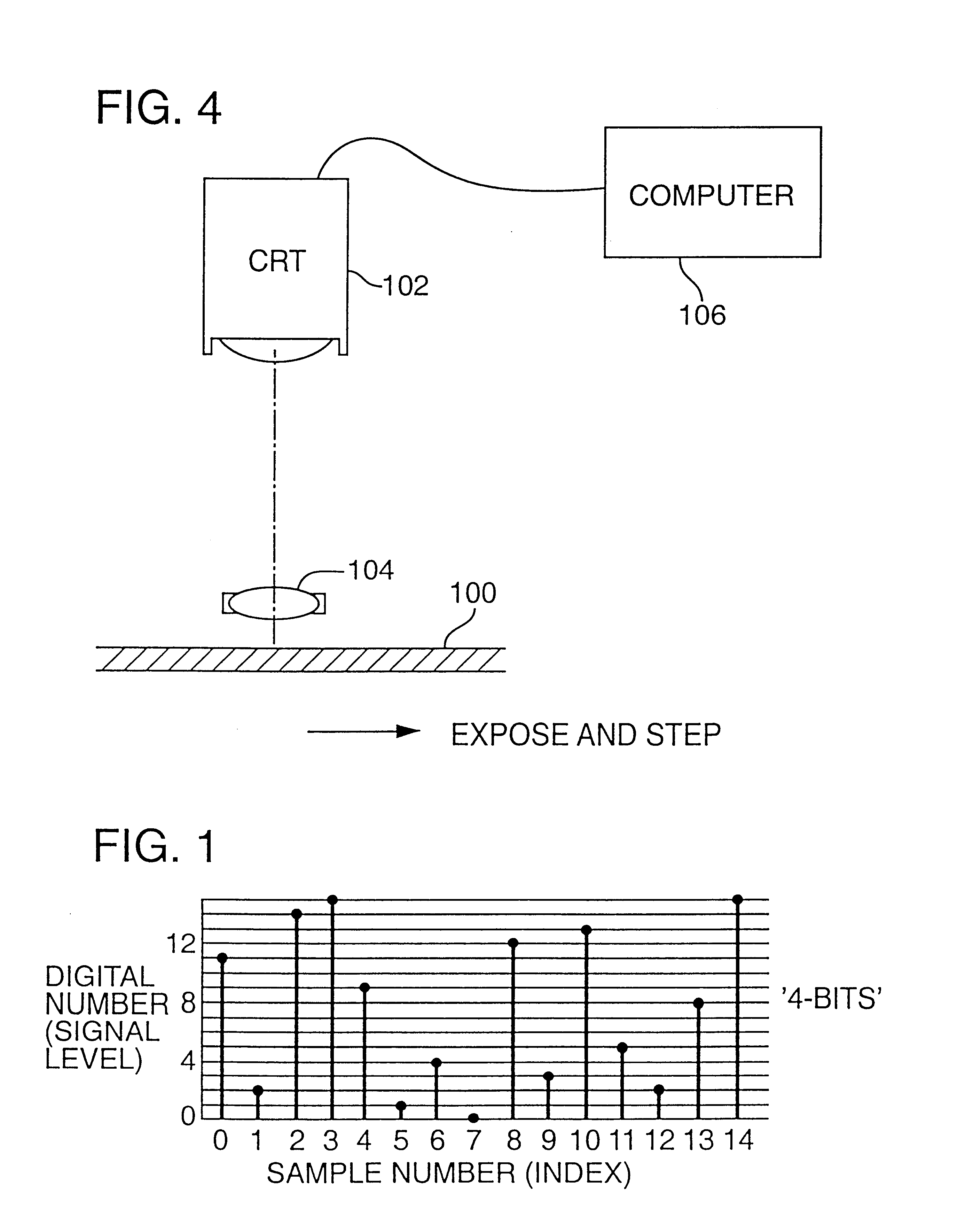
Assume the picture is transformed into a positive color print. We first scan this into a digitized form via a normal high quality black and white scanner with a typical photometric spectral response curve. (It is possible to get better ultimate signal to noise ratios by scanning in each of the three primary colors of the color image, but this nuance is not central to describing the basic process.) Let us assume that the scanned image now becomes a 4000 by 4000 pixel monochrome digital image with a grey scale accuracy defined by 12-bit grey values or 4096 allowed levels. We will call this the “original digital image” realizing that this is the same as our “origin...

second embodiment

In this second embodiment, the PRN data used for encoding and decoding can be as simple or complex as desired. A simple system may use the same PRN data for each call. Such data may be generated, e.g., by a deterministic PRN generator seeded with fixed data unique to the telephone and known also by the central station (e.g. a telephone identifier), or a universal noise sequence can be used (i.e. the same noise sequence can be used for all telephones). Or the pseudo random data can be generated by a deterministic PRN generator seeded with data that changes from call to call (e.g. based on data transmitted during call set-up identifying, e.g., the destination telephone number, etc.). Some embodiments may seed the pseudo random number generator with data from a preceding call (since this data is necessarily known to the telephone and the carrier, but is likely not known to pirates).

Naturally, elements from the foregoing two approaches can be combined in various ways, and supplemented b...


PUM


Abstract

A tile-based arrangement is employed to effect watermarking of plural-bit auxiliary data into still or moving digital images. In a particular embodiment, the plural-bit auxiliary data is represented as a rectangular block of overlay data. This block is repetitively tiled, both vertically and horizontally, across the image, and combined with the image data to effect the encoding.

Description

BACKGROUNDHiding data in imagery or audio is a technique well known to artisans in the field, and is termed “steganography.” There are a number of diverse approaches to, and applications of, steganography. A brief survey follows:British patent publication 2,196,167 to Thorn EMI discloses a system in which an audio recording is electronically mixed with a marking signal indicative of the owner of the recording, where the combination is perceptually identical to the original. U.S. Pat. Nos. 4,963,998 and 5,079,648 disclose variants of this system.U.S. Pat. No. 5,319,735 to Bolt, Berenak & Newman rests on the same principles as the earlier Thorn EMI publication, but additionally addresses psycho-acoustic masking issues.U.S. Pat. Nos. 4,425,642, 4,425,661, 5,404,377 and 5,473,631 to Moses disclose various systems for imperceptibly embedding data into audio signals—the latter two patents particularly focusing on neural network implementations and perceptual coding details.U.S. Pat. No. 4...

Claims


Application Information

Patent Timeline
IPC IPC(8): B42D15/10G07F17/26G06K9/20G06T1/00G07C9/00G07D7/12G07D7/00G06F17/30G10L19/00G07F17/00G07F7/10G07F17/16G11B20/00G07F7/08G07F7/12G06K19/14G06K19/06G06K19/18G06K7/14H04B1/66H04N7/26H04N1/00H04N5/913H04N1/32G06K17/00H04Q7/38G06V30/40
CPCG06F17/30876B42D25/00G06K7/1417G06K7/1447G06K9/00442G06K19/06037G06K19/06046G06K19/14G06K19/18G06Q20/341G06Q20/40145G06T1/005G07C9/00079G07D7/0013G07D7/002G07D7/004G07F7/08G07F7/086G07F7/1008G07F7/1016G07F7/12G10L19/018G11B20/00086G11B20/00094G11B20/00166G11B20/0021G11B20/00884G11B20/00891H04B1/665H04N1/00005H04N1/00037H04N1/00079H04N1/32144H04N1/3216H04N1/32203H04N1/32208H04N1/32251H04N1/32288H04N1/32352H04N5/913H04N21/23892H04N21/8358H04N19/00H04N19/467G06K7/14G06K2017/0064G06K2019/06253G06T2201/0052H04N1/32122H04N2005/91321H04N2005/91335H04N2201/3205H04N2201/3207H04N2201/3225H04N2201/3226H04N2201/3233H04N2201/327H04N2201/3271H04N2201/3274H04N2201/328G07D7/0032G07D7/0034G06F16/955G07C9/253G06V30/40B42D25/333B42D25/23G06T1/0021
Inventor RHOADS, GEOFFREY B.
Owner DIGIMARC CORP (FORMERLY DMRC CORP)
Why Eureka
Try Eureka