Video coding and video decoding apparatus

a video coding and video decoding technology, applied in the field of video coding apparatus and video decoding apparatus, can solve the problem of reducing the coding efficiency of alpha-map codes

Inactive Publication Date: 2005-04-12
KK TOSHIBA
View PDF13 Cites 4 Cited by
  • Summary
  • Abstract
  • Description
  • Claims
  • Application Information

AI Technical Summary

Benefits of technology

It is an object of the present invention to provide a video coding apparatus and a video decoding apparatus capable of efficiently encoding and decoding alpha-map information which is subsidiary video information representing the shape of an object and the position of the object in the frame.

Problems solved by technology

This increase in the alpha-map code amount decreases the coding efficiency.

Method used


Image

  • Video coding and video decoding apparatus
  • Video coding and video decoding apparatus
  • Video coding and video decoding apparatus

Examples


sixth embodiment

The foregoing is an example of the processing in which macro blocks MB are compression-encoded one after another in raster scan order and decoded in raster scan order (order of x-direction scan in x-y scan). However, when macro blocks MB are compression-encoded and decoded one after another, the compression processing can be performed more efficiently, depending on the state of a picture, when performed in the vertical direction (in order of y-direction scan in x-y scan) than when performed in raster scan order. Therefore, it is useful to realize a method capable of selectively performing processing in raster order or in the vertical direction in accordance with the state of a picture. This method will be described below as the

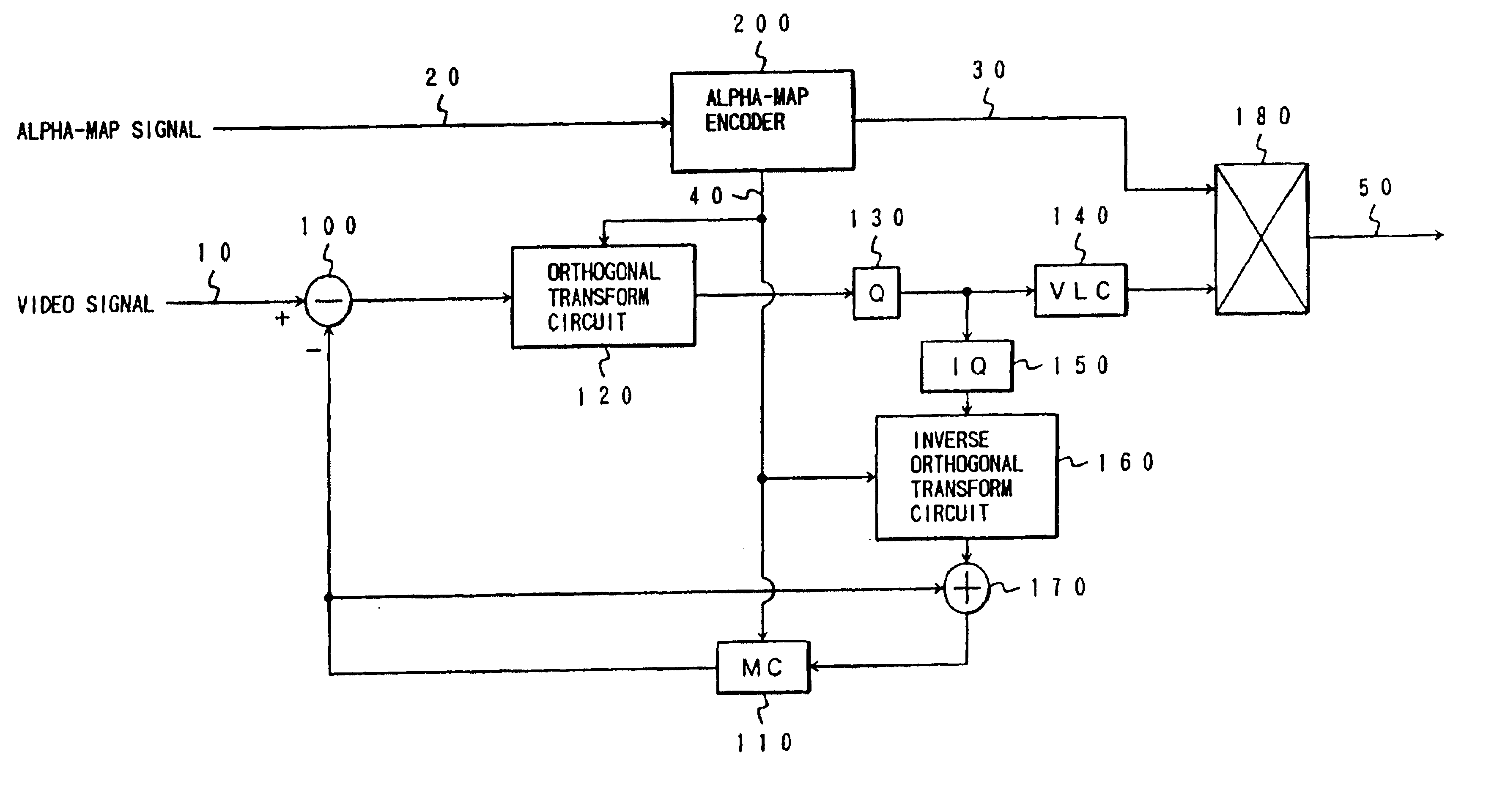
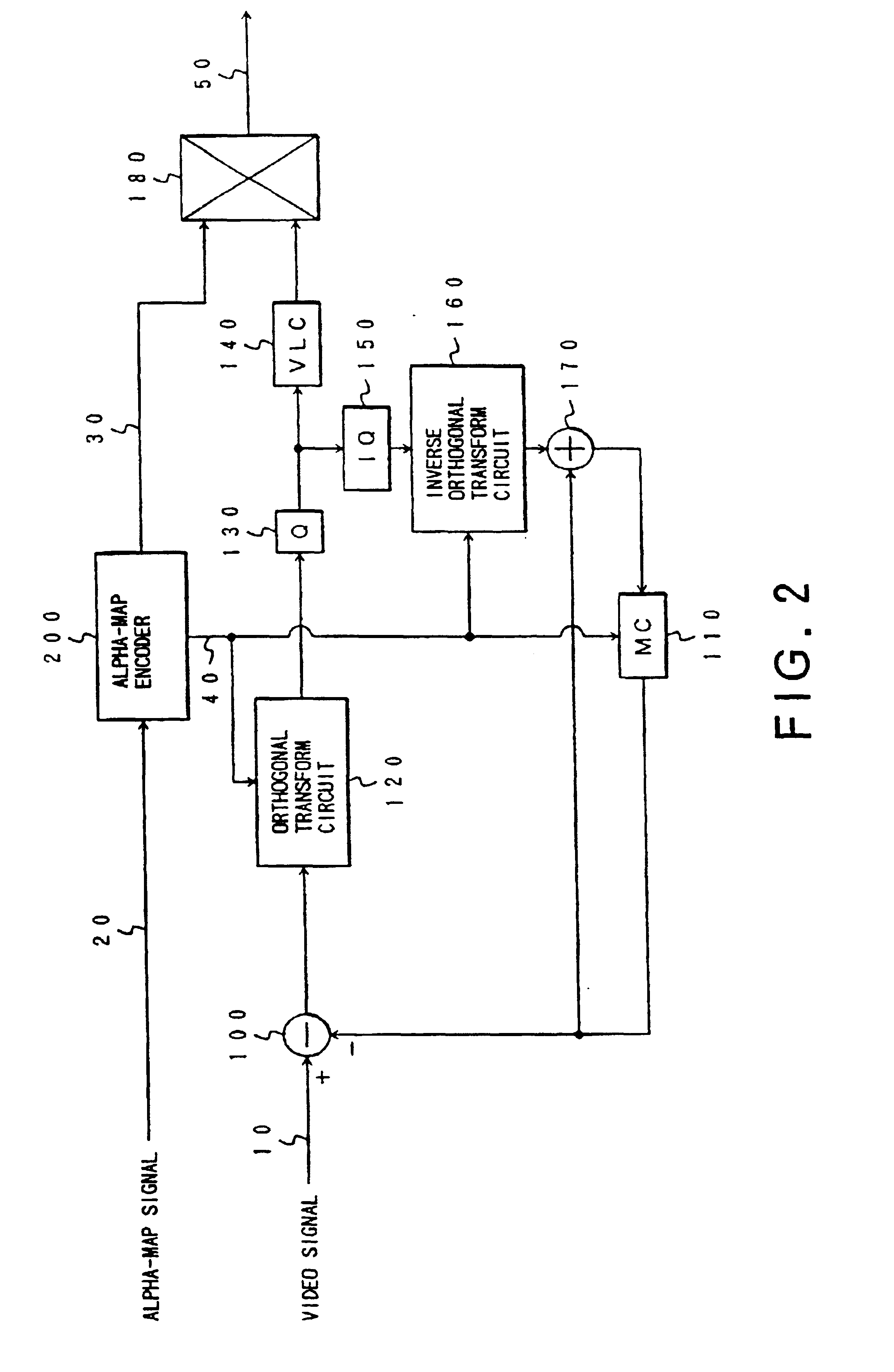
The sixth embodiment of the present invention will be described below with reference to FIGS. 38A to 38D. System configurations required in this embodiment can also be basically the same as the configurations shown in FIGS. 2 and 3. That is, it is only necessa...

seventh embodiment

It is, however, in some instances also possible to reduce the amount of codes by processing macro blocks MB, as square blocks, after rearranging them into wide rectangular blocks, instead of directly processing them in the form of a square block. This method will be described below as the

The seventh embodiment of the present invention will be described below with reference to FIGS. 39A to 39C. System configurations required in this embodiment can also be basically the same as the configurations shown in FIGS. 2 and 3. It is only necessary to design the system such that encoding is performed by the alpha-map encoder 200 shown in FIG. 2 and decoding is performed by the alpha-map decoder 400 shown in FIG.3.

In this embodiment, the values of “top reference” and “left reference” in the fifth embodiment are not used in order to independently encode macro blocks MB.

FIG. 39A is a view for explaining the scan order of this embodiment. A square block of n×n pixels constituting the macro block ...

eighth embodiment

Even in the processing of macro blocks MB, it is in many instances inefficient to directly compress blocks with the macro block size. For example, when every line in a macro block MB assumes the same state of a picture such as when only a vertical belt-like line exists in a picture, data can be faithfully reproduced without decreasing the resolution even if the data is compressed while lines are thinned. An optimum method for a picture like this will be described below as the

The eighth embodiment of the present invention will be described below with reference to FIGS. 6, 8, and 40A and 40B. System configurations required in this embodiment can also be basically the same as the configurations shown in FIGS. 2 and 3. It is only necessary to design the system such that encoding is performed by the alpha-map encoder 200 shown in FIG. 2 and decoding is performed by the alpha-map decoder 400 shown in FIG. 3.


PUM


Abstract

A video encoding apparatus is provided with a resolution converting section, an encoding section, and a transmitting section. The resolution converting section enlarges or reduces a binary picture which represents the shape of an object. The encoding section encodes a binary picture reduced by the resolution converting section. The reduction ratio used by the resolution converting section is encoded, and the transmitting section transmits this encoded reduction ratio along with encoded data on the binary picture. The amount of encoded data produced from the encoding section is controlled by changing the enlargement / reduction ratio used by the resolution converting section.

Description

BACKGROUND OF THE INVENTION1. Field of the InventionThe present invention relates to a video coding apparatus and a video decoding apparatus for encoding a video signal at a high efficiency, transmitting and storing the coded signal, and decoding the coded signal.2. Description of the Related ArtGenerally, a video signal is compression-encoded before being transmitted or stored because the signal has an enormous amount of information. To encode a video signal at a high efficiency, a picture or an image of a frame is divided into a plurality of blocks in units of a predetermined number of pixels. Orthogonal transformation is performed for each block to separate the special frequency of a picture into frequency components. Each frequency component is obtained as a transform coefficient and encoded.As one video coding system, a video coding system belonging to a category called mid-level coding is proposed in J. Y. A. Wang et. al., “Applying Mid-level Vision Techniques for Video Data C...

Claims


Application Information

Patent Timeline
Patent Type & Authority Patents(United States)
IPC IPC(8): G06T3/40H04N7/26H04N7/46
CPCG06T3/40G06T3/4023H04N19/59H04N19/29H04N19/20
Inventor YAMAGUCHI, NOBORUWATANABE, TOSHIAKIIDA, TAKASHIKURATATE, TAKAAKI
Owner KK TOSHIBA
Why Eureka
Try Eureka