System and process for generating high dynamic range video

a high-dynamic range and video technology, applied in the field of high-dynamic range (hdr) video production, can solve the problems of not giving the details of the registration step and its robustness, the typical video footage captured using an off-the-shelf camcorder suffers from limited dynamic rang

Inactive Publication Date: 2005-04-12
MICROSOFT TECH LICENSING LLC
View PDF8 Cites 155 Cited by
  • Summary
  • Abstract
  • Description
  • Claims
  • Application Information

AI Technical Summary

Benefits of technology

For each quadrant in each hierarchical level not itself further segmented into quadrants, a portion of the flow field associated with the quadrant under consideration is computed using the homography computed for and assigned to that quadrant. Otherwise, the portion of the flow field associated with the quadrant under consideration is computed using the homography assigned to the quadrant in the previous level, from which the quadrant under consideration in the current level was segmented. Finally, a feathering technique can be applied to the flow components residing within the overlapping regions of the quadrants to minimize flow discontinuities across the resulting flow field.

Problems solved by technology
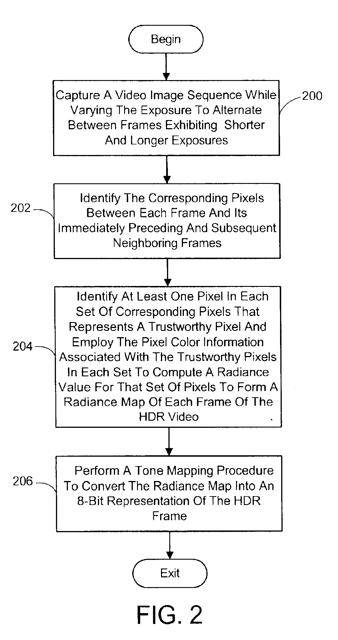
However, details of the registration step and its robustness were not given.
However, none of these previous image-based methods is designed to efficiently create HDR video.
Typical video footage captured using an off-the-shelf camcorder suffers from limited dynamic range.
In addition, the prior methods would not allow a conventional video camera to be used to create HDR video.

Method used


Image

  • System and process for generating high dynamic range video
  • System and process for generating high dynamic range video
  • System and process for generating high dynamic range video

Examples


Embodiment Construction

In the following description of the preferred embodiments of the present invention, reference is made to the accompanying drawings which form a part hereof, and in which is shown by way of illustration specific embodiments in which the invention may be practiced. It is understood that other embodiments may be utilized and structural changes may be made without departing from the scope of the present invention.

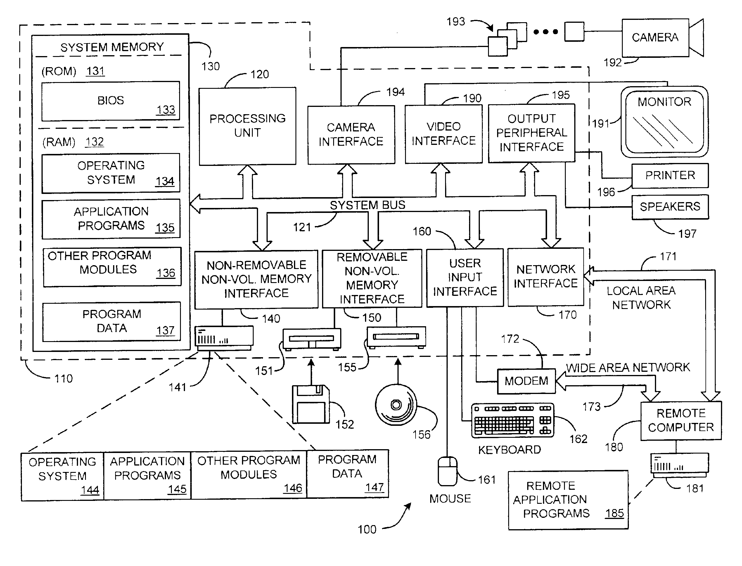
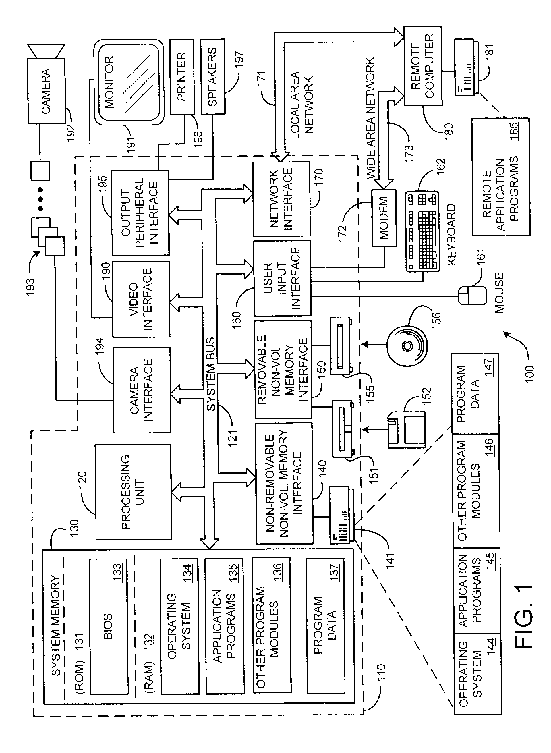
1.0 The HDR Video Generating System Computing Environment

Before providing a description of the preferred embodiments of the present invention, a brief, general description of a suitable computing environment in which the invention may be implemented will be described. FIG. 1 illustrates an example of a suitable computing system environment 100. The computing system environment 100 is only one example of a suitable computing environment and is not intended to suggest any limitation as to the scope of use or functionality of the invention. Neither should the computing environment...


PUM


Abstract

A system and process for generating High Dynamic Range (HDR) video is presented which involves first capturing a video image sequence while varying the exposure so as to alternate between frames having a shorter and longer exposure. The exposure for each frame is set prior to it being captured as a function of the pixel brightness distribution in preceding frames. Next, for each frame of the video, the corresponding pixels between the frame under consideration and both preceding and subsequent frames are identified. For each corresponding pixel set, at least one pixel is identified as representing a trustworthy pixel. The pixel color information associated with the trustworthy pixels is then employed to compute a radiance value for each pixel set to form a radiance map. A tone mapping procedure can then be performed to convert the radiance map into an 8-bit representation of the HDR frame.

Description

BACKGROUND1. Technical FieldThe invention is related to producing High Dynamic Range (HDR) video, and more particularly to a system and process for generating HDR video from a video image sequence captured while varying the exposure of each frame.2. Background ArtThe real world has a lot more brightness variation than can be captured by the sensors available in most cameras today. The radiance of a single scene may contain four orders of magnitude in brightness—from shadows to fully lit regions. Typical CCD or CMOS sensors only capture about 256-1024 brightness levels.This limited dynamic range problem has inspired many solutions in recent years. One method of capturing the full radiance of a static scene is to take multiple exposures of the scene and then to combine them to create a High Dynamic Range (HDR) map [3, 7, 10]. The static scene requirement can be eliminated using multiple image detectors, novel sensors or spatially varying pixel exposures [8]. Mann et al. [6] register d...

Claims


Application Information

Patent Timeline
Patent Type & Authority Patents(United States)
IPC IPC(8): H04N5/235H04N5/77H04N5/781H04N5/85
CPCG06T5/50H04N5/235H04N5/2352H04N5/77H04N5/2355H04N5/85H04N5/781H04N23/72H04N23/70H04N23/741G06T5/40
Inventor KANG, SING BINGUYTTENDAELE, MATTHEW T.WINDER, SIMONSZELISKI, RICHARD
Owner MICROSOFT TECH LICENSING LLC
Why Eureka
Try Eureka