Method and system for assisting a user taking measurements using a coordinate measurement machine

a technology of coordinate measurement machine and measurement method, which is applied in the direction of electrical programme control, instruments, program control, etc., can solve the problems of time-consuming and limited measurement and quality inspection function in the manufacturing process, unreliable, and inconvenient use, and achieves the effect of reducing labor intensity, improving accuracy, and improving accuracy

Inactive Publication Date: 2005-04-12
FARO TECH INC
View PDF16 Cites 102 Cited by
  • Summary
  • Abstract
  • Description
  • Claims
  • Application Information

AI Technical Summary

Problems solved by technology

Yet measuring the assemblies made of these parts against the CAD model, for the most part, has continued to remain unwieldy, expensive, and unreliable.
Traditionally, the measurement and quality inspection function in the manufacturing process has been time-consuming and limited in size, scope, and effectiveness for a number of reasons.
Manual measurement tools, such as calipers and scales may be slow, imprecise, and always one-dimensional.
Analog test fixtures are costly and inflexible.
As a result, CMMs measure only small, readily-moved subassemblies and components—which often translates into significant “down time” for the production line.
This last phase of the CAD revolution has remained incomplete because of the significant technical demands for adaptive measurement hardware and usable CAD-based measurement software for the difficult manufacturing environment.
Geometric dimensioning and tolerancing (GD&T) requirements further complicated the inspection process.
Without GD&T, a designer might arbitrarily and unknowingly define a part's tolerances too tight for cost effective manufacturing.
Prior automated systems did not track datum designations and relied on the user to select part features corresponding to datums identified in the formal drawing from a generic list of measured features, making the tolerance evaluation unnecessarily tedious and prone to mistakes.

Method used


Image

  • Method and system for assisting a user taking measurements using a coordinate measurement machine
  • Method and system for assisting a user taking measurements using a coordinate measurement machine
  • Method and system for assisting a user taking measurements using a coordinate measurement machine

Examples


Embodiment Construction

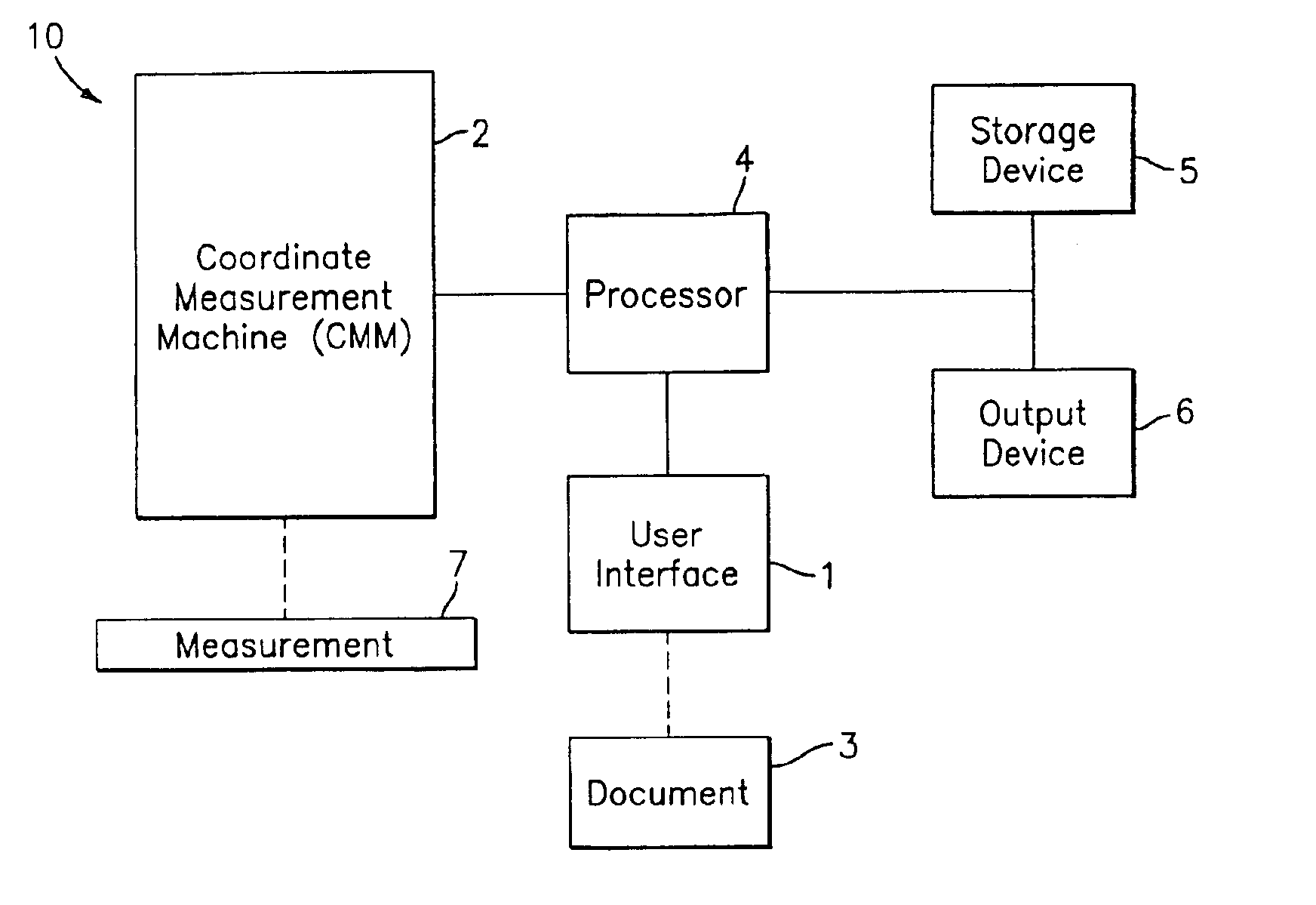
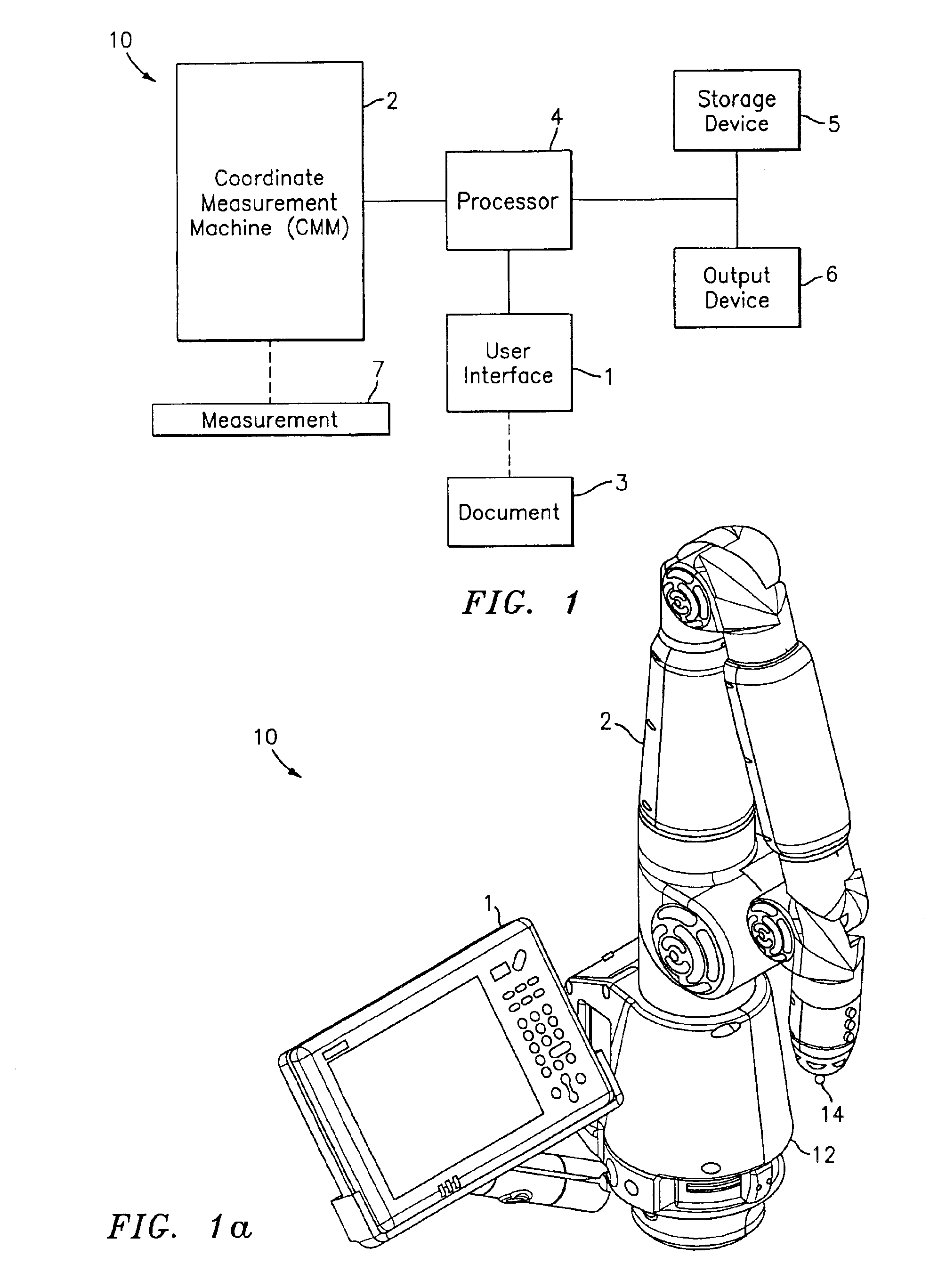
FIG. 1 is a block diagram of an exemplary system 10 for assisting a user taking measurements of a target 7 using a coordinate measurement machine (CMM) 2. Target 7 is a part or other object to be tested to determine whether it conforms to GD&T requirements that were defined at design-time. Document 3 contains GD&T data (specifications) of one or more features of target 7 and CMM 2 measures these features on target 7.

As disclosed herein, document 3 may also be representative of GD&T data that is communicated to the user orally or embedded into a digital definition of the target, e.g., in a CAD / CAM database. System 10 may include a processor 4 in operative communication with the CMM 2 providing a user interface 1 to receive a feature measurement and corresponding GD&T data, and to determine whether the measured feature is acceptable based on the GD&T data.

User interface 1 may include a monitor, touchscreen, keyboard, mouse and / or the like. Also, the user interface 1 may include a suit...


PUM


Abstract

A method and system for testing a target object for compliance with existing geometric dimension and tolerance requirements includes: measuring a selected feature of the target and entering the existing geometric dimension and tolerance requirements into a user interface. Entering includes selecting an icon containing a graphic symbol representative of a geometric dimension and tolerance characteristic.

Description

BACKGROUNDThe invention relates in general to coordinate measurement machines (CMMs) and in particular to a method and system for assisting a user taking measurements using a CMM.The manufacturing / industrial marketplace took on a new face during the 1980's with the introduction of computer-aided design (CAD) and computer-aided manufacturing (CAM). While CAD allowed engineers to produce 3-D images in the front end of the design process, which shortened the production cycle and led to tremendous gains in productivity, CAM software and equipment increased the efficiency and quality of machined single parts. In essence, these new technologies revolutionized the marketplace by increasing productivity, improving quality, and reducing costs.Despite these technological advances in design and manufacturing, something important was missing from the production cycle: a highly accurate, efficient, and convenient measurement methodology for ensuring that the products and components—both on and o...

Claims


Application Information

Patent Timeline
Patent Type & Authority Patents(United States)
IPC IPC(8): G01B21/02G01B11/00G01B21/04G05B19/04G05B19/00G05B19/042
CPCG01B11/005G05B19/0423G05B19/00G01B21/04
Inventor STEFFEY, KENNETHSCHENCK, TOMPERREAULT, DANATWELL, PAUL
Owner FARO TECH INC
Why Eureka
Try Eureka