Method for routing connections in the display of a network topology

a topology and network technology, applied in the field of computer user interfaces, can solve the problems of ever increasing complexity and density, difficult to achieve efficient, organized and aesthetically pleasing routing, especially in “real time”, and achieve the effect of fast uniform and effective routing

Active Publication Date: 2005-04-12
AVAGO TECH INT SALES PTE LTD
View PDF12 Cites 35 Cited by
  • Summary
  • Abstract
  • Description
  • Claims
  • Application Information

AI Technical Summary

Benefits of technology

The routing procedure operates at different layers, groups and subgroups of nodes. By using the procedure with a layered design it is possible to achieve fast uniform and effective routing in very complex systems with many nodes and internode connections.

Problems solved by technology

Although there are many applications that effectively use computer graphics to provide an efficient user interface, problems arise due to the ever-increasing complexity and density of the information to be displayed.
However, while it is desirable for a system to automatically perform routing and display of connections in a network topology application it is often difficult to achieve efficient, organized and aesthetically pleasing routing, especially in “real time.” This is especially true where the number of nodes and connections is relatively large.

Method used


Image

  • Method for routing connections in the display of a network topology
  • Method for routing connections in the display of a network topology
  • Method for routing connections in the display of a network topology

Examples


Embodiment Construction

A preferred embodiment of the invention is incorporated into a software product called “SANavigator” produced and distributed by SANavigator, Inc.

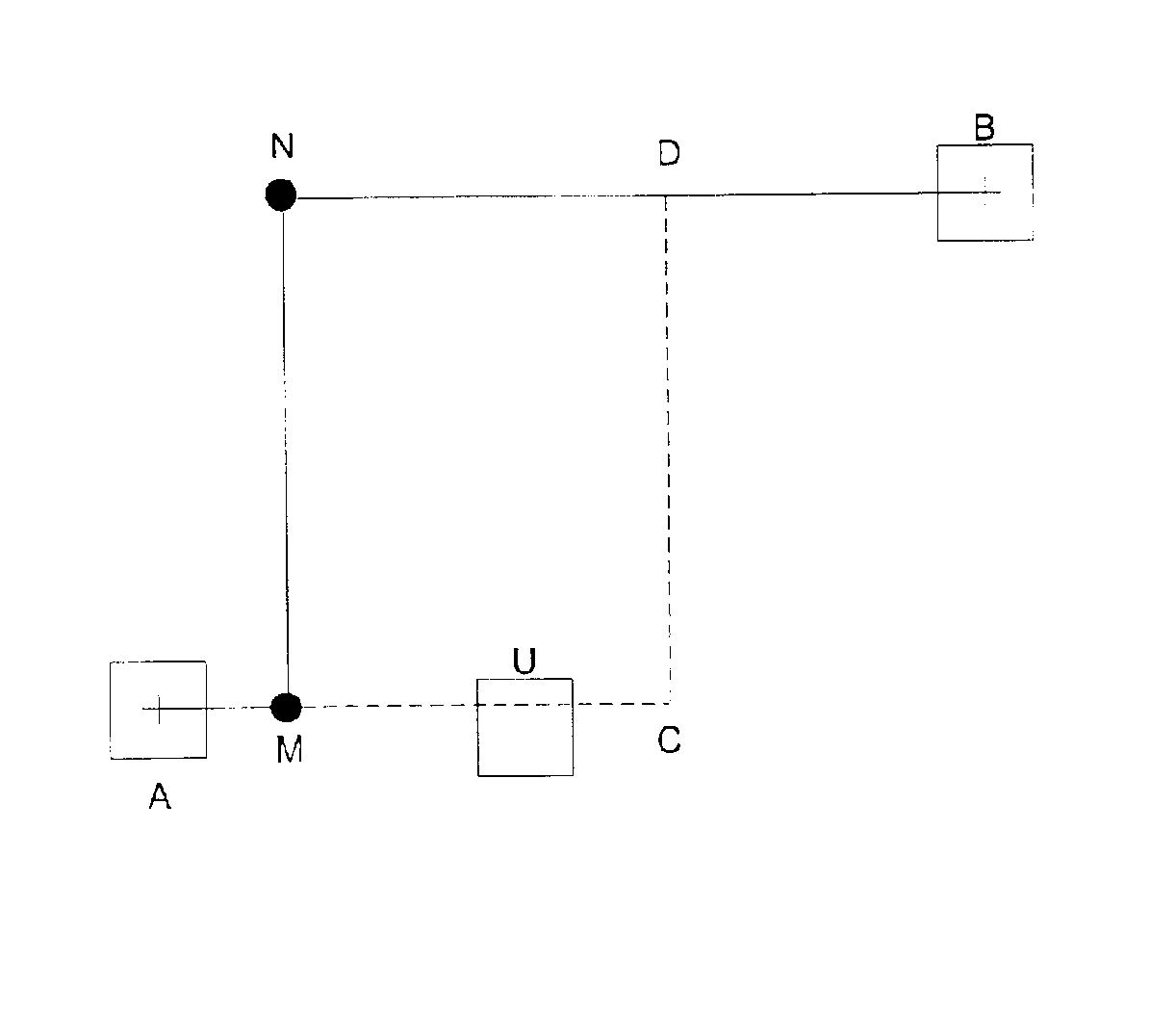
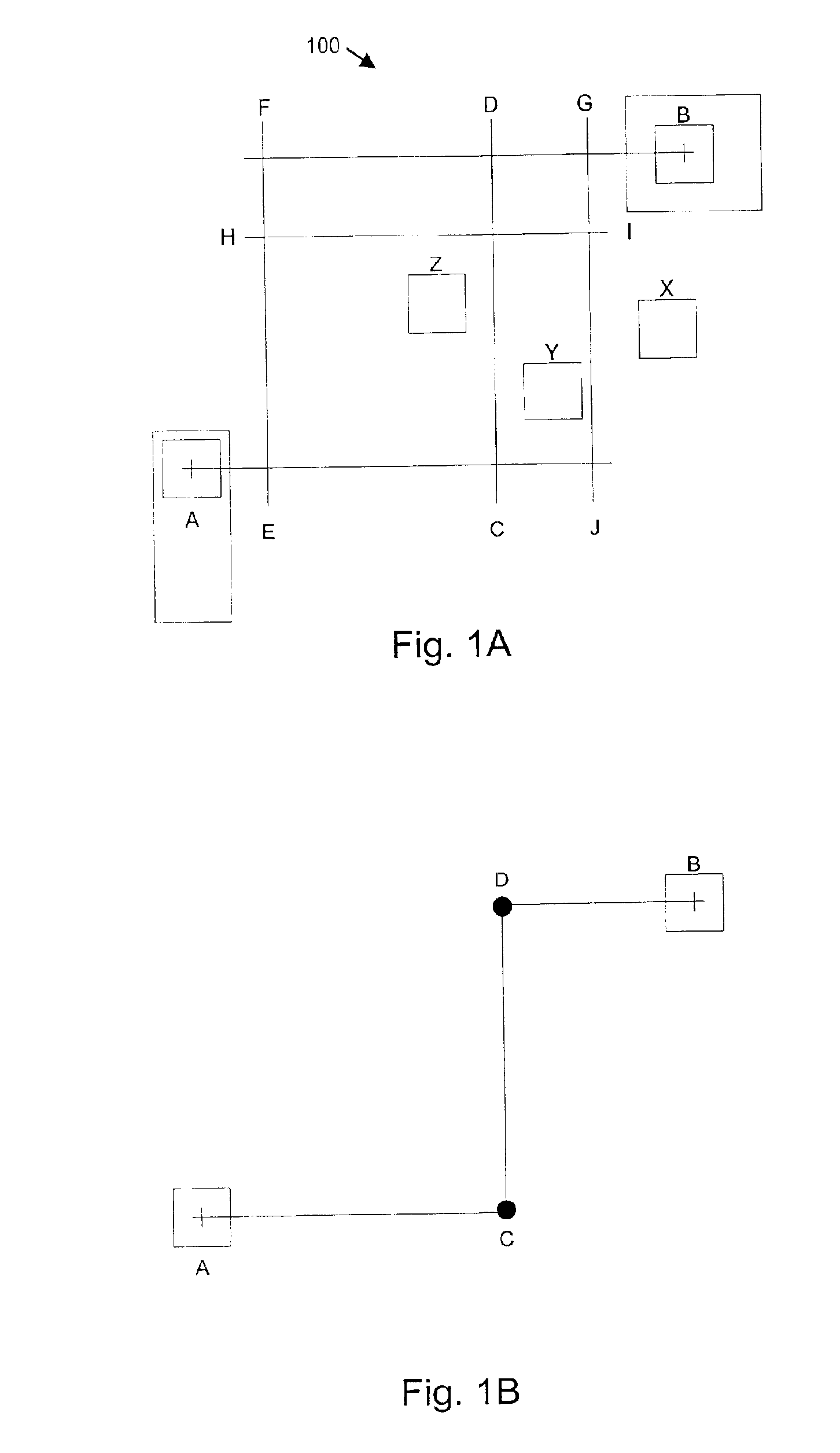
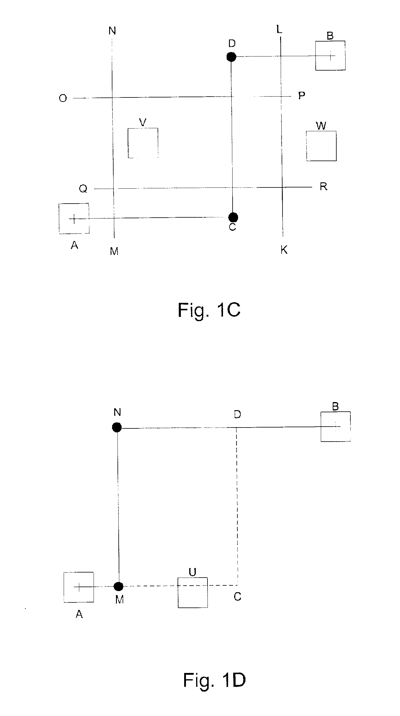
FIG. 1A illustrates a portion of a screen display of the SANavigator interface of the present invention.

In FIG. 1A, screen display portion 100 includes interconnected nodes A and B. Nodes include any type of network device such as a hub, server, switch, servers, client processors, computers, routers, etc. Typically, a node can be any type of hardware device or functionality that is of interest in analyzing, creating or managing a communications network. Further, as described in the above-referenced related applications, a preferred embodiment of the present invention allows nodes to be grouped into “group nodes” which can then be represented as a single icon, or node, in a multilayer representation.

A group node of a second layer in a multilayer representation can be selectively expanded to display nodes contained in a first layer. A lower ...


PUM


Abstract

The present invention provides a systematic automated procedure for routing connections in display applications such as a network topology interface. In one embodiment, the invention first creates an “ideal routing” between two given nodes. The ideal routing includes three segments that join the nodes. If any obstructions exist on the original segments of the ideal routing then the procedure systematically reroutes the appropriate segments to achieve an efficient, visually cohesive and organized routing. The routing procedure operates at different layers, groups and subgroups of nodes. By using the procedure with a layered design it is possible to achieve fast, uniform and effective routing in very complex systems with many nodes and inter-node connections.

Description

BACKGROUND OF THE INVENTIONThis invention relates in general to computer user interfaces and more specifically to a method for automatically routing and displaying connections between nodes in a network topology displayed on a computer user interface.Computer graphics has become an important application for computer systems. The ability to clearly and effectively display information in a graphical form has spawned many useful computer programs such as for computer-assisted drawing (CAD), electronic and microelectronic circuit layout, network topology display and network management, etc.Although there are many applications that effectively use computer graphics to provide an efficient user interface, problems arise due to the ever-increasing complexity and density of the information to be displayed. For example, today's networks have many components, or nodes, including servers, disk arrays, routers, hubs, switches, clients, etc. Each node may have several, or many, connections to ot...

Claims


Application Information

Patent Timeline
Patent Type & Authority Patents(United States)
IPC IPC(8): G06F15/16G06T11/20G06F17/50
CPCH04L41/12G06T11/206Y10S715/964
Inventor ARQUIE, LOUIS
Owner AVAGO TECH INT SALES PTE LTD
Why Eureka
Try Eureka