Torque sensor and electric power steering system having same
a technology of torque sensor and electric power steering, which is applied in the direction of force/torque/work measurement apparatus, instruments, transportation and packaging, etc., can solve the problems of complex construction of detecting device, affecting the reliability of detecting device, and prone to deterioration of brush and slip ring reliability, etc., to achieve cost saving, less number of components, and compact and inexpensive effect of torque sensor
- Summary
- Abstract
- Description
- Claims
- Application Information
AI Technical Summary
Benefits of technology
Problems solved by technology
Method used
Image

Examples
first embodiment
(First Embodiment)
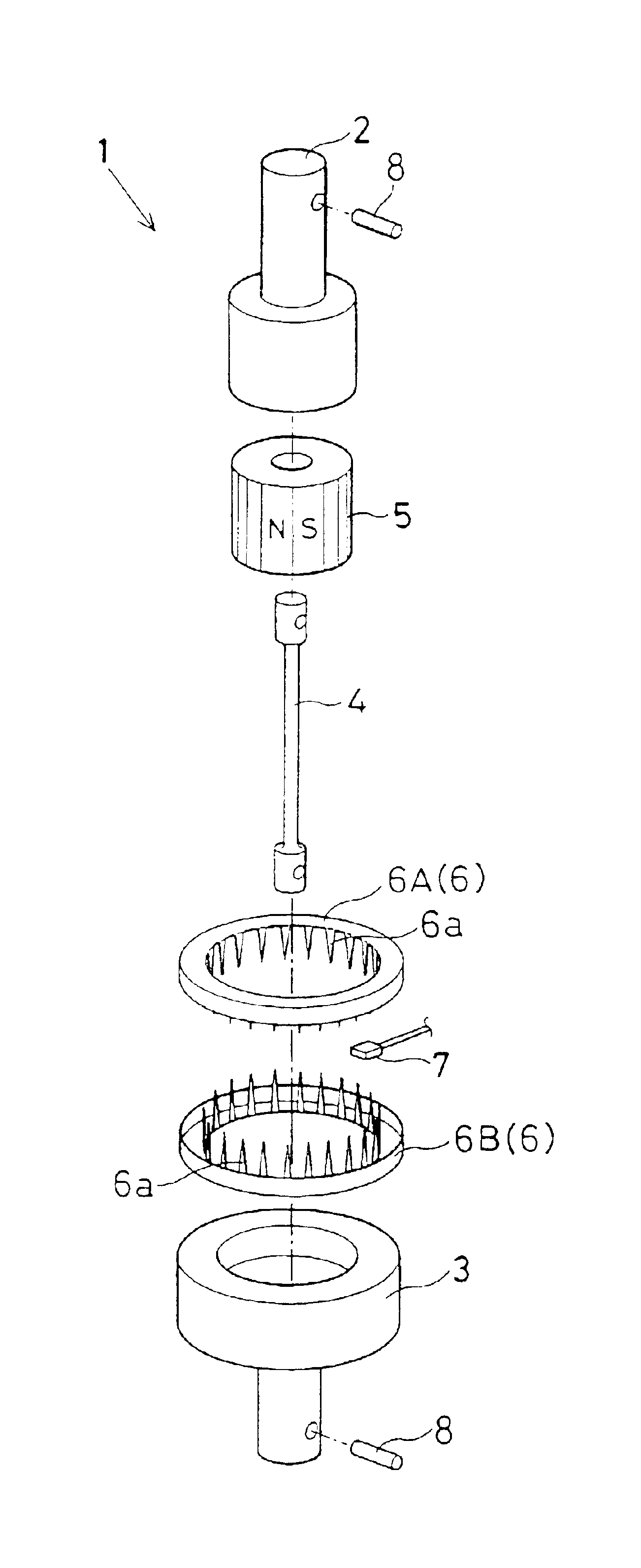
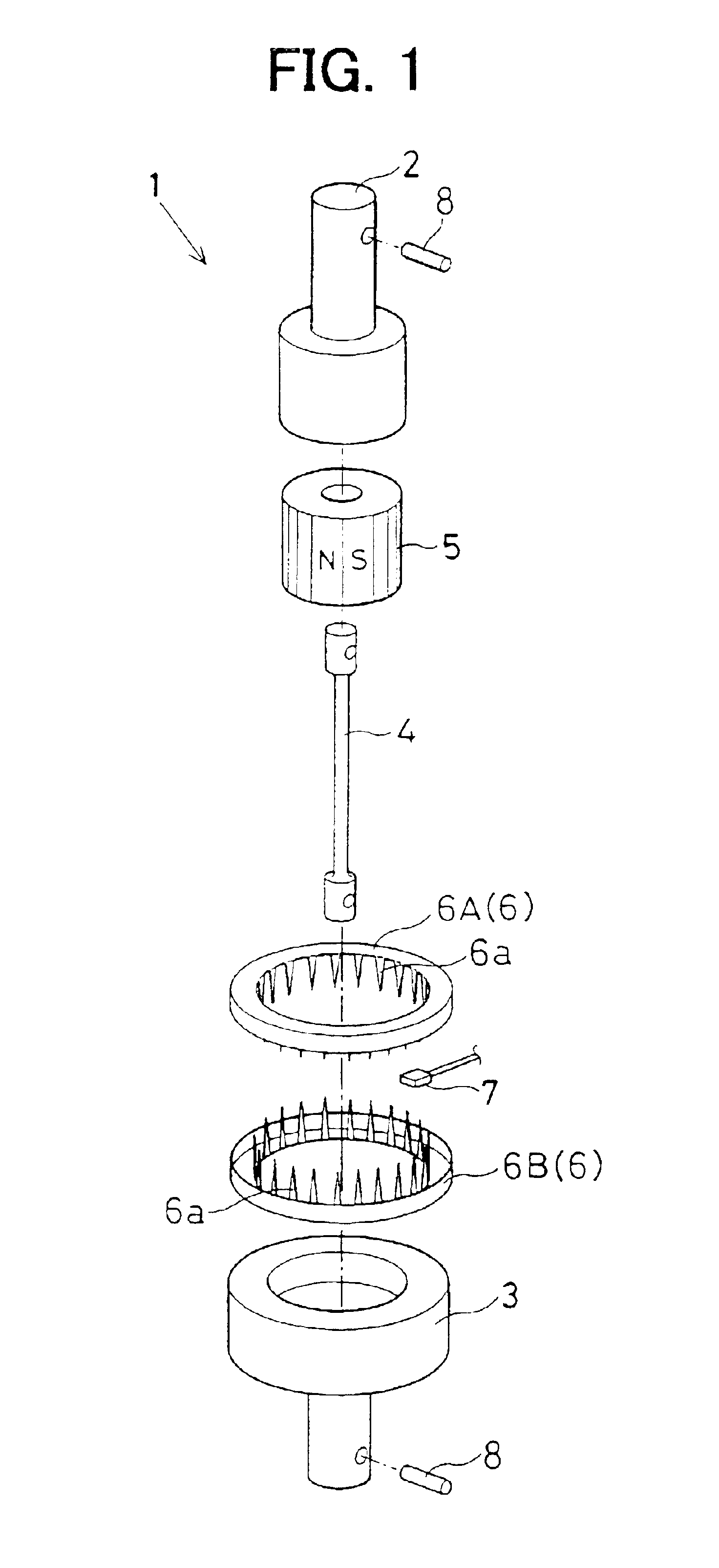
[0062]A torque sensor 1 according to a first embodiment is described with reference to FIGS. 1 to 4D.
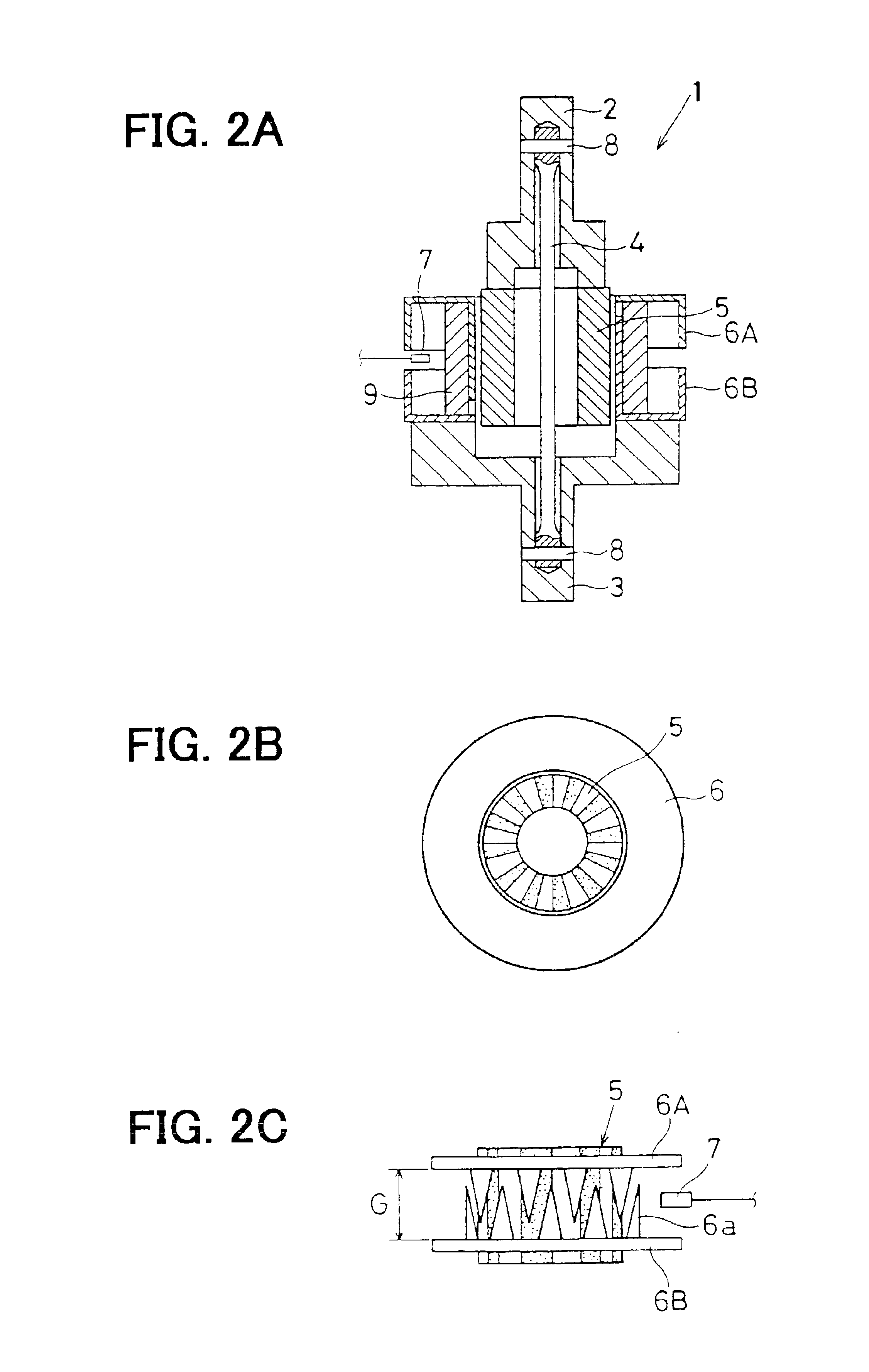
[0063]FIG. 1 shows an exploded perspective view of the torque sensor 1. FIG. 2A is a cross sectional view of the torque sensor 1. FIGS. 2B and 2C show plan and elevation views of a magnet and magnetic yokes, respectively.
[0064]The torque sensor 1 is applicable, for example, to an electric power steering system for a vehicle (refer to FIG. 17) and disposed between an input shaft 2 and an output shaft 3 that constitute a steering shaft. The torque sensor 1 is for detecting steering torque applied to the steering shaft.
[0065]The torque sensor 1 is composed of a torsion bar 4 (resilient member) connecting coaxially the input shaft 2 and the output shaft 3, a magnet 5 (ferromagnetic member) fixed to an axial end of the input shaft 2 on a side of the output shaft 3, a pair of magnetic yokes 6 (soft magnetic member) fixed to an axial end of the output shaft 3 and a magneti...
second embodiment
(Second Embodiment)
[0085]A torque sensor 1 according to a second embodiment is described with reference to FIGS. 5 and 6.
[0086]FIG. 5 shows an exploded perspective view of a torque sensor 1. FIG. 6 is a cross sectional view of the torque sensor 1.
[0087]The torque sensor 1 according to the second embodiment has a pair of magnetic flux collective rings 10 (auxiliary soft magnetic member) in addition to components of the first embodiment.
[0088]Each of the magnetic flux collective rings 10 (10A, 10B) is made of same soft magnetic material as the magnetic yokes 6 and formed in a ring shape. The magnetic flux collective rings 10A and 10B are positioned around and in a vicinity of outer circumferences of the magnetic yokes 6A and 6B, respectively.
[0089]Each of the magnetic flux collective rings 10 is provided at a circumferential position thereof with a flat collective plate 10a. The collective plates 10a of the magnetic flux collective rings 10A and 10B are axially opposed to each other. ...
third embodiment
(Third Embodiment)
[0091]A torque sensor 1 according to a third embodiment is described with reference to FIG. 7. FIG. 7 shows an exploded perspective view of a part of the torque sensor 1.
[0092]The torque sensor 1 according to the third embodiment has two magnetic sensors 2 which are positioned in the axial gap between the magnetic yokes 6A and 6B. Magnetism detecting directions of the respective magnetic sensors 7 are opposite to each other, as shown in arrows marks in FIG. 7. Each of the magnetic sensors 7 is connected to a differential circuit 11. The differential circuit 11 outputs a torque signal after output signals from the magnetic sensors 7, which are input to the differential circuit 11, are processed differentially therein.
[0093]In case of a single magnetic sensor 7, the detection fluctuation due to a position where the magnetic sensor is located is relatively large. However, as the torque sensor 1 according to the third embodiment has two magnetic sensors 7, the detectin...
PUM
 Abstract
Description
Claims
Application Information
 - R&D
- Intellectual Property
- Life Sciences
- Materials
- Tech Scout
- Unparalleled Data Quality
- Higher Quality Content
- 60% Fewer Hallucinations
Browse by: Latest US Patents, China's latest patents, Technical Efficacy Thesaurus, Application Domain, Technology Topic, Popular Technical Reports.
© 2025 PatSnap. All rights reserved.Legal|Privacy policy|Modern Slavery Act Transparency Statement|Sitemap|About US| Contact US: help@patsnap.com