Journal bearing for trolley wheel

Active Publication Date: 2005-04-19
FROST TECH
View PDF4 Cites 33 Cited by
  • Summary
  • Abstract
  • Description
  • Claims
  • Application Information

AI Technical Summary

Benefits of technology

[0006]The present invention is intended to provide a bearingless trolley wheel assembly which provides for low friction rolling of the trolley wheel about a hub and which can withstand high temperatures and caustic cle

Problems solved by technology

However, the bearings typically require lubrication and may contaminate various paint processes if the oils or lubricants bleed or leak or drip from the bearings as the wheel assembly and trolley travel through the paint processes.
Also, pre-paint cleaning operations and the like typically use highl

Method used


Image

  • Journal bearing for trolley wheel
  • Journal bearing for trolley wheel
  • Journal bearing for trolley wheel

Examples


Example

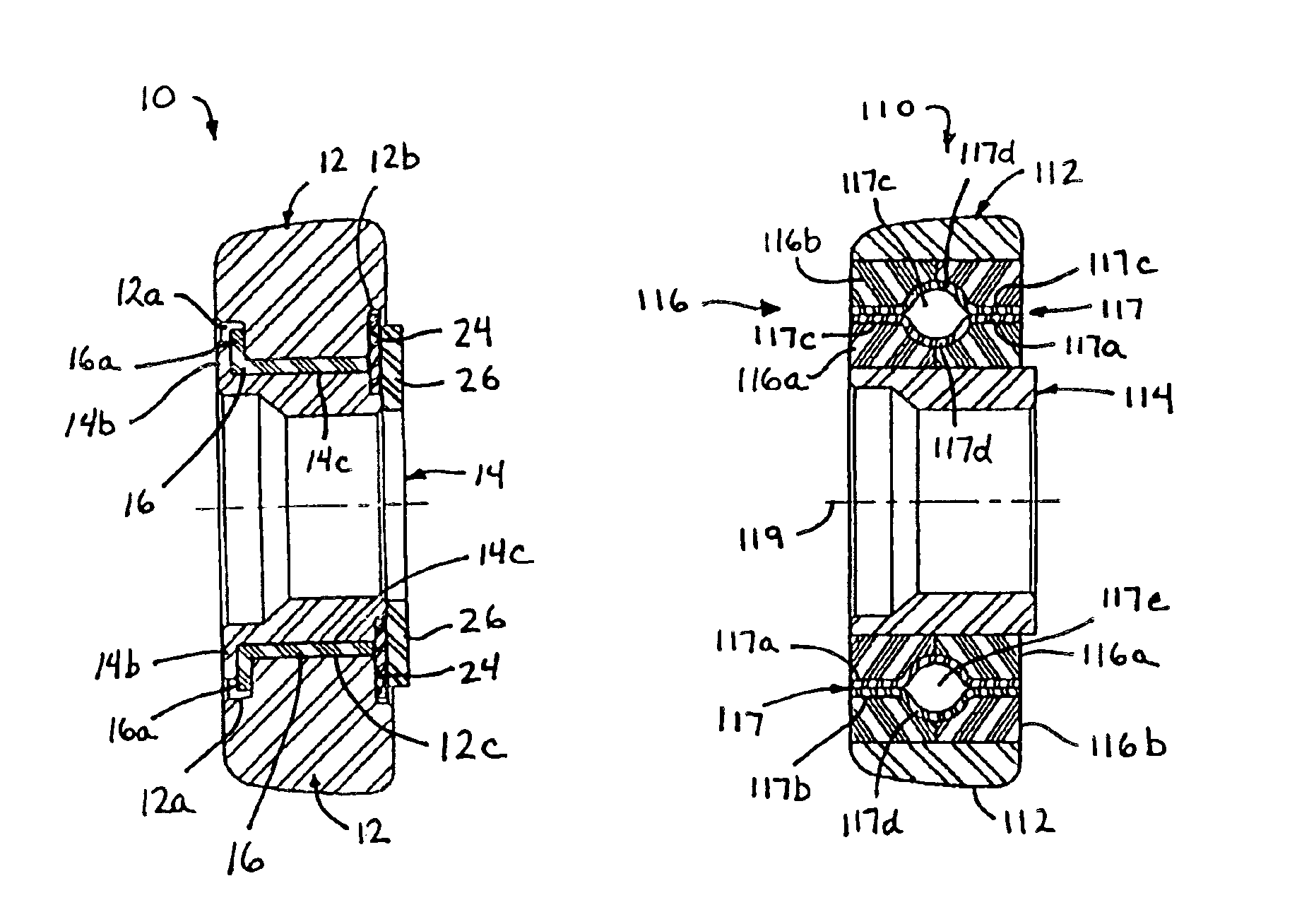
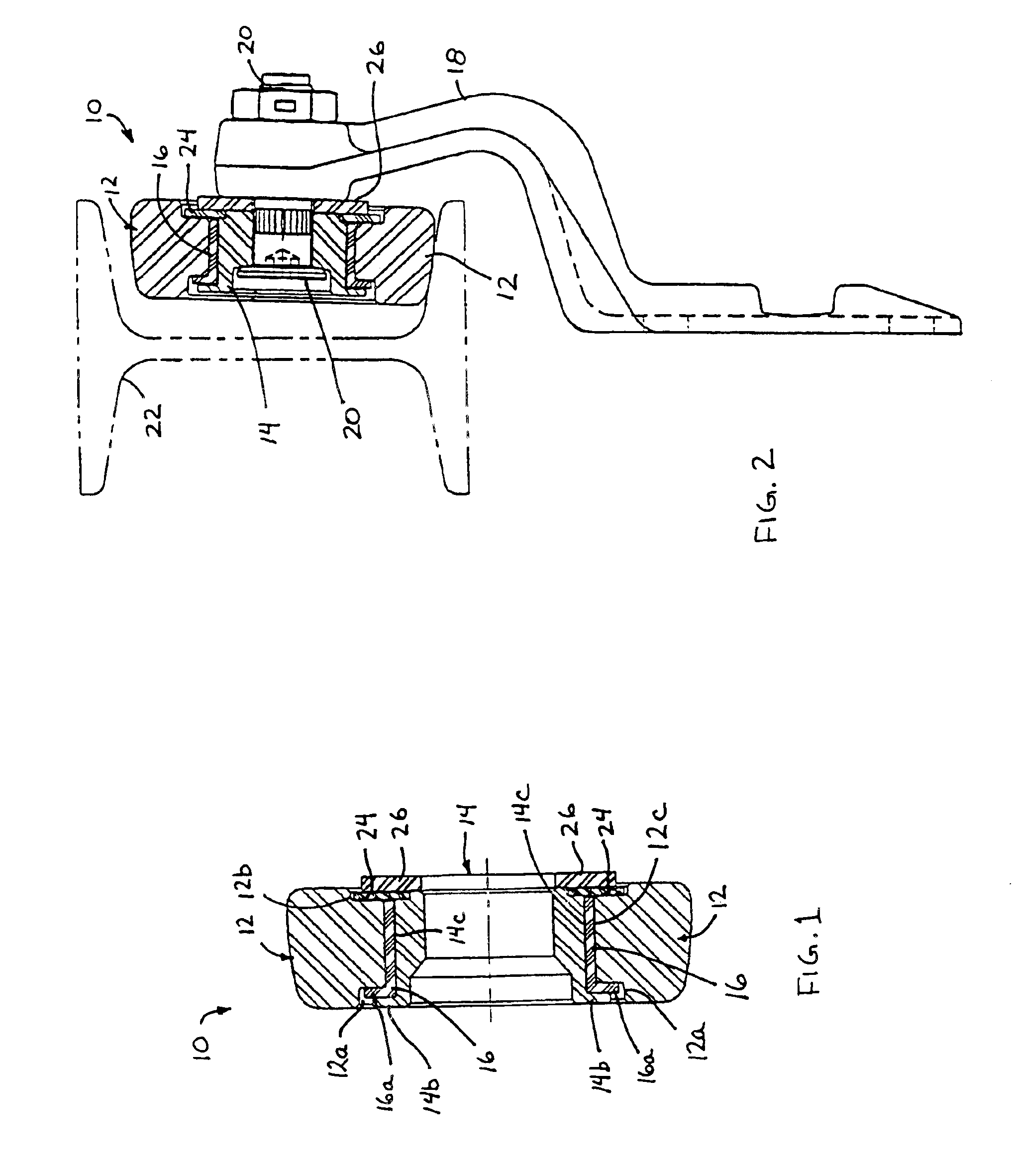
[0032]Referring now to the drawings and the illustrative embodiments depicted therein, a trolley wheel assembly 10 comprises a metal wheel portion 12, a metal or steel hub portion 14 and a plastic journal bearing member 16 positioned or sandwiched between the wheel portion 12 and hub portion 14 (FIGS. 1 and 2). The plastic journal bearing 16 comprises an engineered thermoplastic, low friction compound or material, which provides for smooth, low friction rolling of wheel portion 12 relative to hub portion 14 of wheel assembly 10.

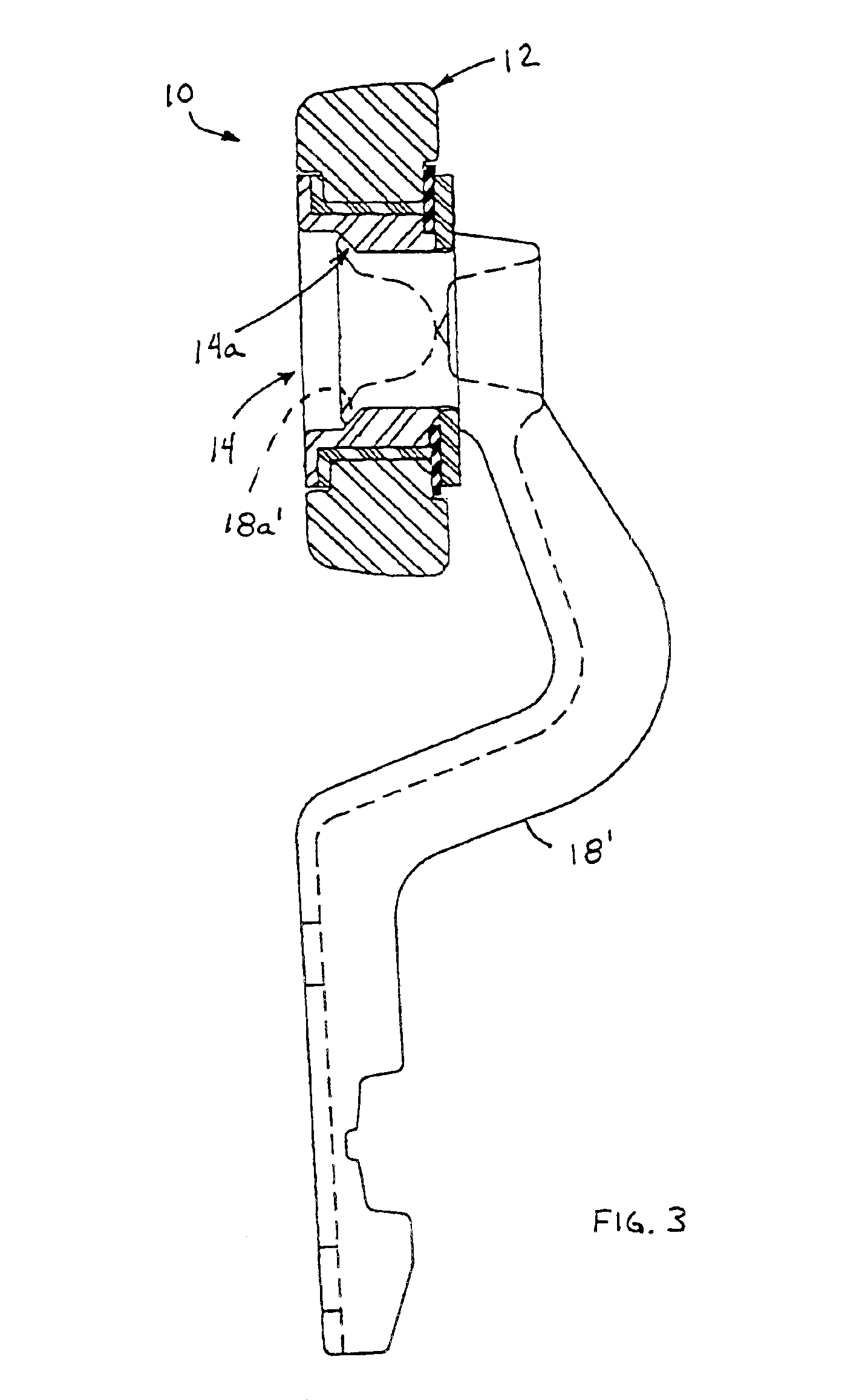
[0033]As shown in FIG. 2, wheel assembly 10 may be part of a bolt-on wheel and trolley construction, where the wheel assembly 10 is bolted to a trolley arm 18 via a bolt 20 or other fastener. The hub portion 14 is thus secured to the arm portion 18, whereby wheel portion 12 rotates about hub portion 14 as the wheel assembly 10 and arm 18 travels along an I-beam 22 or the like of a trolley conveyor system. Optionally, as shown in FIG. 3, the wheel assembly of ...


PUM


Abstract

A trolley wheel assembly includes a wheel portion rotatably positioned around a hub portion and at least one sliding member positioned between the wheel portion and the hub portion. The sliding member defines a mating surface for mating with a generally correspondingly formed mating surface of the wheel portion and/or the hub portion. The mating surface of the sliding member defines a radial projection at least substantially circumferentially around the sliding member. The radial projection may slidably mate with the generally correspondingly formed mating surface of the wheel portion and/or the hub portion to facilitate rotation of the wheel portion about the hub portion. The wheel assembly may include one or more inserts that define the correspondingly formed mating surface and that are positioned between the sliding member and the wheel or hub portion to facilitate manufacturing and assembly of the wheel assembly.

Description

CROSS REFERENCE TO RELATED APPLICATION[0001]The present application claims benefit of U.S. provisional application Ser. No. 60 / 429,361, filed Nov. 26, 2002 by Frost for LOW FRICTION JOURNAL BEARING FOR TROLLEY WHEEL, which is hereby incorporated herein by reference in its entirety.FIELD OF THE INVENTION[0002]The present invention relates generally to trolley wheel assemblies and, more particularly, to a wheel assembly for a trolley that is suitable for use in adverse environments.BACKGROUND OF THE INVENTION[0003]Conveyor trolleys typically have bearings between the wheel and the hub of each trolley wheel assembly to allow for smooth, generally low friction rolling of the wheel relative to the hub and trolley arm. However, the bearings typically require lubrication and may contaminate various paint processes if the oils or lubricants bleed or leak or drip from the bearings as the wheel assembly and trolley travel through the paint processes. Also, pre-paint cleaning operations and th...

Claims


Application Information

Patent Timeline
IPC IPC(8): B65G39/00B65G17/20B65G39/09B65G39/20F16C13/00
CPCB65G17/20F16C13/006B65G39/20B65G39/09A01B71/04B61B3/00B61B7/00B61B11/00
Inventor FROST, CHARLES C.
Owner FROST TECH
Why Eureka
Try Eureka