Solar air conditioning system

a solar energy and air conditioning technology, applied in the field of energy saving solar energy air conditioning systems for buildings, can solve the problems of environmental destruction, solar collector details, and environmental damage, and achieve the effects of maximizing the introduction of cooled air, reducing environmental pollution, and increasing the overall heat-absorbing efficiency of the entire system

Inactive Publication Date: 2005-04-19
INST NUCLEAR ENERGY RES ROCAEC
View PDF7 Cites 46 Cited by
  • Summary
  • Abstract
  • Description
  • Claims
  • Application Information

AI Technical Summary

Benefits of technology

[0027]In addition, toward the direction of the heat-absorbing channels, both the inlet and outlet assemblies have a blank side for connecting to the transparent panel of two ends of the solar collector assembly. Once the panel connects with the sides, the connections should be sealed. As to the inlet and outlet assemblies, they are fixed to the roof or other fixed boards. An air distributor is respectively located at the joints where the inlet assembly connects to the indoor exhaust pipes and the joints where the outlet assembly connects to the indoor inlet pipes. On such distributors, drilled holes are arranged uniformly on the side facing the heat-absorbing channels. The function of these holes is to evenly distribute air flow into each heat-absorbing channel in order to increase the overall heat-absorbing efficiency of the entire system. By switching and adjusting the openings of indoor pipes and the paths communicating to the outdoors, the heated air can be fanned indoors for heating purposes during wintertime or in cold weather, while during summertime or in hot weather, the air that goes to the indoor exhaust pipes can be heated and expelled outdoors due to the chimney effect caused by thermal buoyancy and the outdoor air from cold locations can be further introduced into the buildings to achieve the effect of air conditioning with cooled air circulation.
[0028]The aforementioned simple and reliable modular ventilation damper assemblies are located on the pre-set openings of the inlet assembly and the outlet assembly. By opening or closing the ventilation damper assemblies, the system can communicate to or be isolated from the outdoor environment. The basic structure of the ventilation damper assembly has multiple blades which are supported on both sides of an outer frame by means of parallel pivots. Each pivot is positioned on a shaft bearing clamped on the outer frame and a fastener is used to lock the bearing. Thus, when being moved to a closed position, the blades will tightly overlap each other and both sides of the outer frame to become sealed up. The operation of the ventilation damper assembly is done with a connecting rod that connects to the blades so that the turning angle of each blade is same. A pulling rod is further secured to one of the blades at a position along the line of pivots. By changing the position of the pulling rod, the blades can be turned from a completely open position to a completely closed position, and the open state of the ventilation damper assembly can be determined. Since the present invention of solar air conditioning system may be installed on roofs or high walls where most people cannot reach, such a pulling rod can be linked to a driving mechanism, such as a rope linking with the pulling rod and passing over a pulley, so that changing the blade position can be achieved by operating the rope.
[0029]Another advantage of this system is that the temperature of the heat-absorbing set can be automatically adjusted in accordance with the weather conditions. For example, in the scorching summer, when the outdoor temperature is very high, the required indoor air change rate will be the maximum, which maximizes the introduction of the cooled air into the buildings. Then, during winter when the required outdoor temperature is usually very low, the indoor air change rate will be the minimum, which minimizes the introduction of the cooled air into the buildings. Moreover, a high adjustability of air circulation is achieved by the easy controllability of the dampers located at an inlet gate (usually close to the floor) and an exhaust gate (usually close to the ceiling) and allows the indoor air change rate to be customized for a comfortable living environment.
[0030]The solar air conditioning system in accordance with the present invention can also be installed to the flat roof of steel-reinforced concrete (SRC) buildings. A better installation method is to fix this system on fixed boards. The boards can be firmly supported by iron frames with clearances between boards and the roof, while facing the sun. The sun-blocking effect caused by the present system will lower the roof temperature and the reduction of heat accumulated on the roof will be directly helpful for the buildings to save energy. In addition, this extra layer of protection on the roof means that the roof will not need too much work in respect to heat insulation.

Problems solved by technology

With increasing CO2 emissions, the global climate has become abnormal and ecological destruction has increased greatly.
However, the solar collectors used presently still have some drawbacks.
(1) The conventional solar collector is too heavy.
Its long-term use may cause a load to some buildings.
(2) The structure of the conventional solar collector is complicated, which makes its installation and maintenance difficult.
Moreover, it increases the costs and thus prolongs the return period.
(3) The conventional solar heating device has poor compatibility and flexibility to match every type of buildings.
(4) The contour of the solar collector is obtrusive and often impairs the aesthete and harmony of the overall appearance of the buildings.
(5) The package of the collector takes up much space and increases the costs for storage, commodity display, and channel marketing.
(6) The integral assembly of the whole-unit product is bulky, making it difficult for the application on a large area and increases installation cost.
Different thermal expansion coefficients of materials may cause thermal stress problems.
(8) The conventional design cannot satisfy clients' senses of participation and achievement by self-installing the collectors.
(9) Some of the conventional designs can only be applicable to the buildings which are under construction and well-planned for its installation. For most existing buildings, the designs are unsuitable.
(10) When air passes over a glazed panel, heat is dissipated unless a double-glazing is used, but it is expensive and troublesome.
(11) Hot water supply systems or liquid systems operated by solar heating have the problems due to potential of freezing and leakage which impede to reach the expected performance.

Method used


Image

  • Solar air conditioning system
  • Solar air conditioning system
  • Solar air conditioning system

Examples


Embodiment Construction

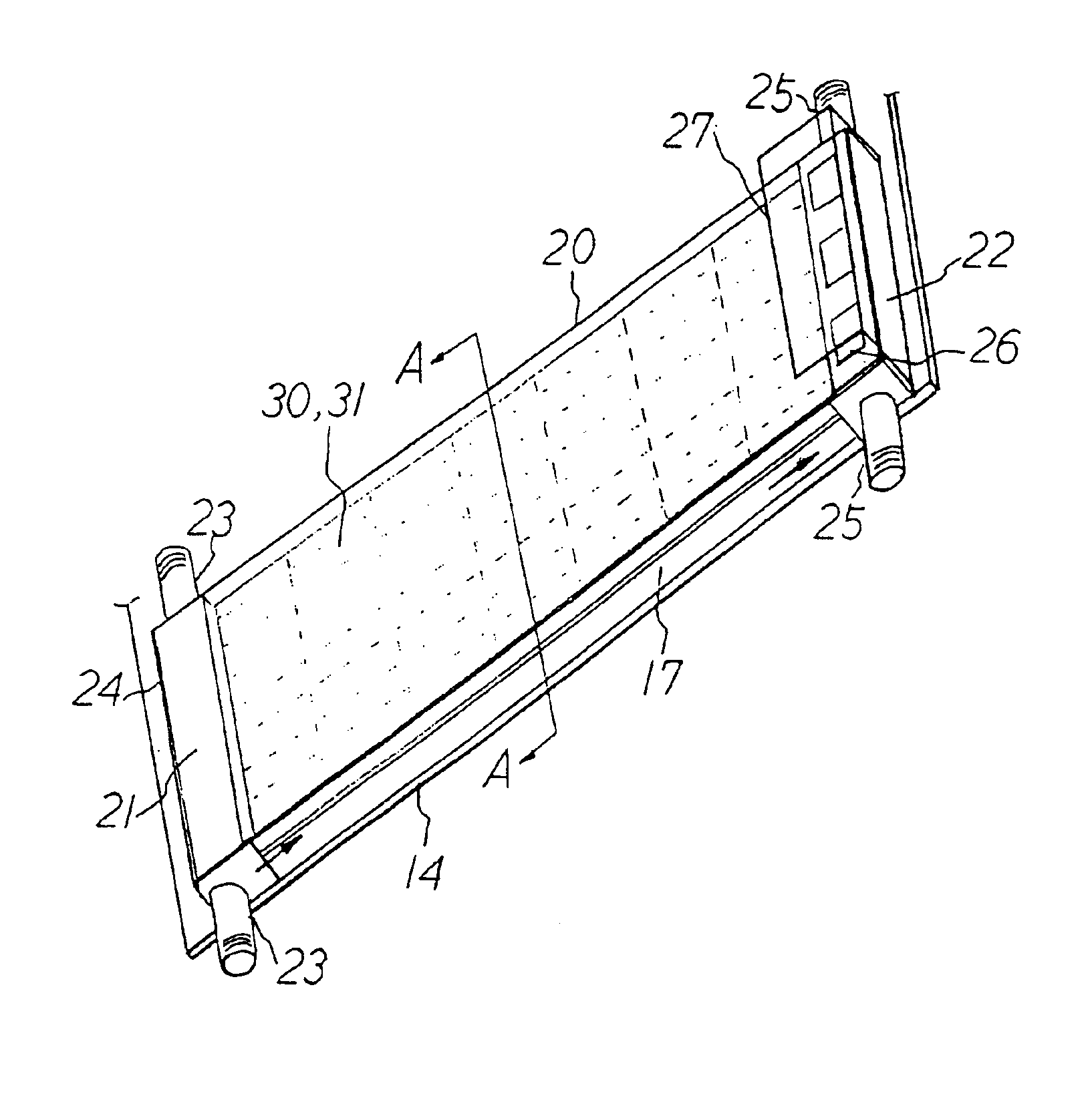
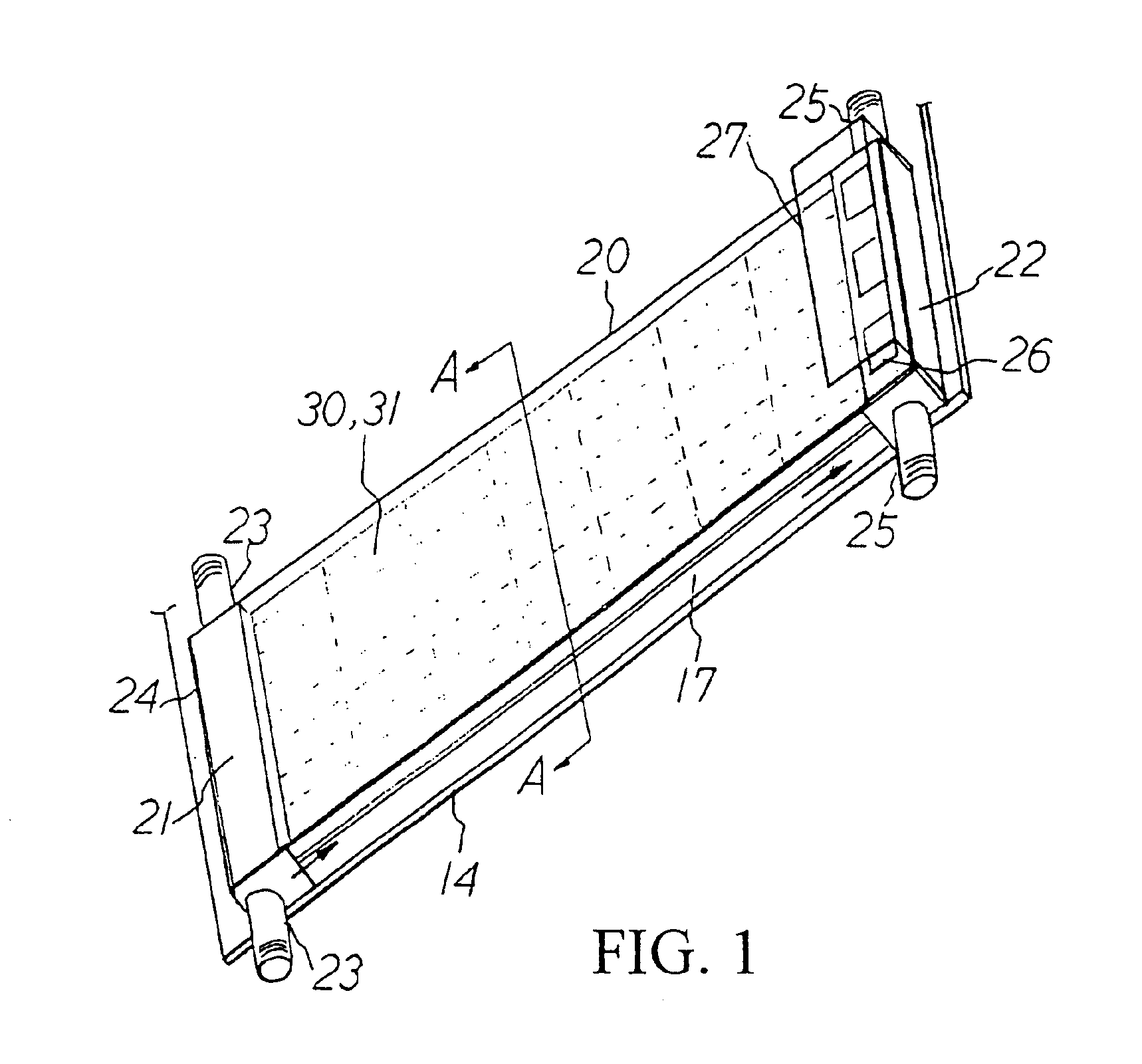
[0050]FIG. 1 is a schematic view of a solar air conditioning system in accordance with the present invention. The air conditioning system includes a solar collector assembly (20), an inlet assembly (21), and an outlet assembly (22). The solar collector assembly (20) forms the paths for heating air and further comprises a heat-absorbing set (17), a transparent panel (30, 31) and a support base (14).

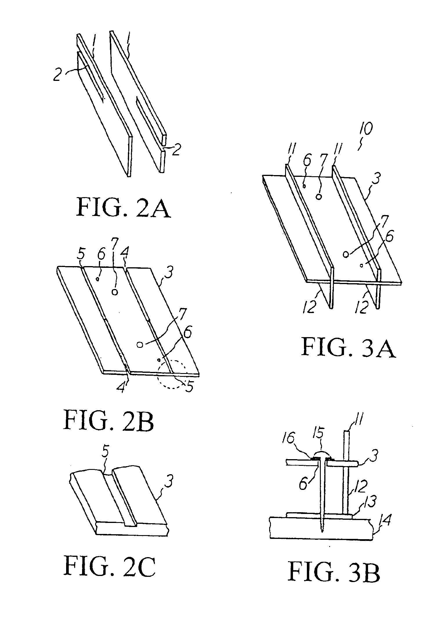
[0051]The heat-absorbing set (17) includes several black modular heat-absorbing units (10). As shown in FIGS. 2A to 2C, a heat-absorbing unit (10) includes two pieces of support boards (1) and a piece of heat-absorbing plate (3). These boards and plate (1, 3) are thin and handy for displaying, packaging, storage, transportation and assembly.

[0052]An elongated groove (2) is formed on the support board (1). The heat-absorbing plate (3) is formed with several heat-absorbing plate fixing holes (6) and several transparent panel fixing holes (7). Also, there is a pair of parallel grooves formed ...


PUM


Abstract

This invention provides buildings with a modular air conditioning system that utilizes solar energy for heating air. This invention contains a solar collector assembly, an inlet assembly and an outlet assembly. The solar collector assembly further comprises a transparent panel, a heat-absorbing set and a support base, and forms paths for heating the air, wherein the heat-absorbing set is made of several simple, light-weight modular heat-absorbing units to form several heat-absorbing channels. Such a design not only can fully utilize the heat-absorbing space on the roof and save the cost for being displayed in marketing channels, but also can be constructed by the users in accordance with their own needs, so as to save cost in modularization. The inlet and outlet assemblies communicate to the heat-absorbing channels in the solar collector assembly and are respectively connected to the pipes and paths leading into and out of the buildings. By switching and adjusting the openings of these pipes and paths, in winter, the preheated air will be introduced into buildings; and in summer, the hot indoor air will be expelled out of the buildings and fresh air will be guided into the buildings. As a result, a more economical air conditioning system is formed.

Description

BACKGROUND OF THE INVENTION[0001]1. Field of the Invention[0002]The present invention relates to an energy-saving solar air conditioning system for buildings. Particularly, the present invention relates to an energy-saving air conditioning system by which, in winter, the preheated air will be introduced into buildings; and in summer, the hot indoor air will be expelled out of the buildings and fresh air will be guided into the buildings.[0003]2. Description of the Related Art[0004]With increasing CO2 emissions, the global climate has become abnormal and ecological destruction has increased greatly. As a result, industrialized countries have again become aware of the urgency to reduce their dependence on fossil fuels after the energy crisis in the 70's. Consequently, these countries have given positive comments on how to use solar energy more effectively. Though the technology field still has reservations about whether solar energy will be able to replace other energy resources in th...

Claims


Application Information

Patent Timeline
Patent Type & Authority Patents(United States)
IPC IPC(8): F24J2/24F24J2/40F24J2/04F24J2/20F24S10/50F24S10/70
CPCF24J2/0488F24J2/202F24J2/40Y02E10/44Y02B10/20F24S10/502F24S50/00F24S70/60
Inventor LIU, TAY-JIANLEE, CHIEN-HSIUNG
Owner INST NUCLEAR ENERGY RES ROCAEC
Why Eureka
Try Eureka