Fuel fill system

a fuel filling system and fuel fill technology, applied in the field of fuel filling systems, can solve the problem of the amount of fuel vapor that can permeate the fuel filling

Inactive Publication Date: 2005-04-19
FLUID ROUTING SOLUTIONS
View PDF12 Cites 35 Cited by
  • Summary
  • Abstract
  • Description
  • Claims
  • Application Information

AI Technical Summary

Problems solved by technology

Recent environmental regulations imposed on the automotive industry and on the fuel delivery industries severely limit the amount of fuel vapor that can permeate from the fuel fill system of motor vehicles.

Method used


Image

  • Fuel fill system
  • Fuel fill system
  • Fuel fill system

Examples


Embodiment Construction

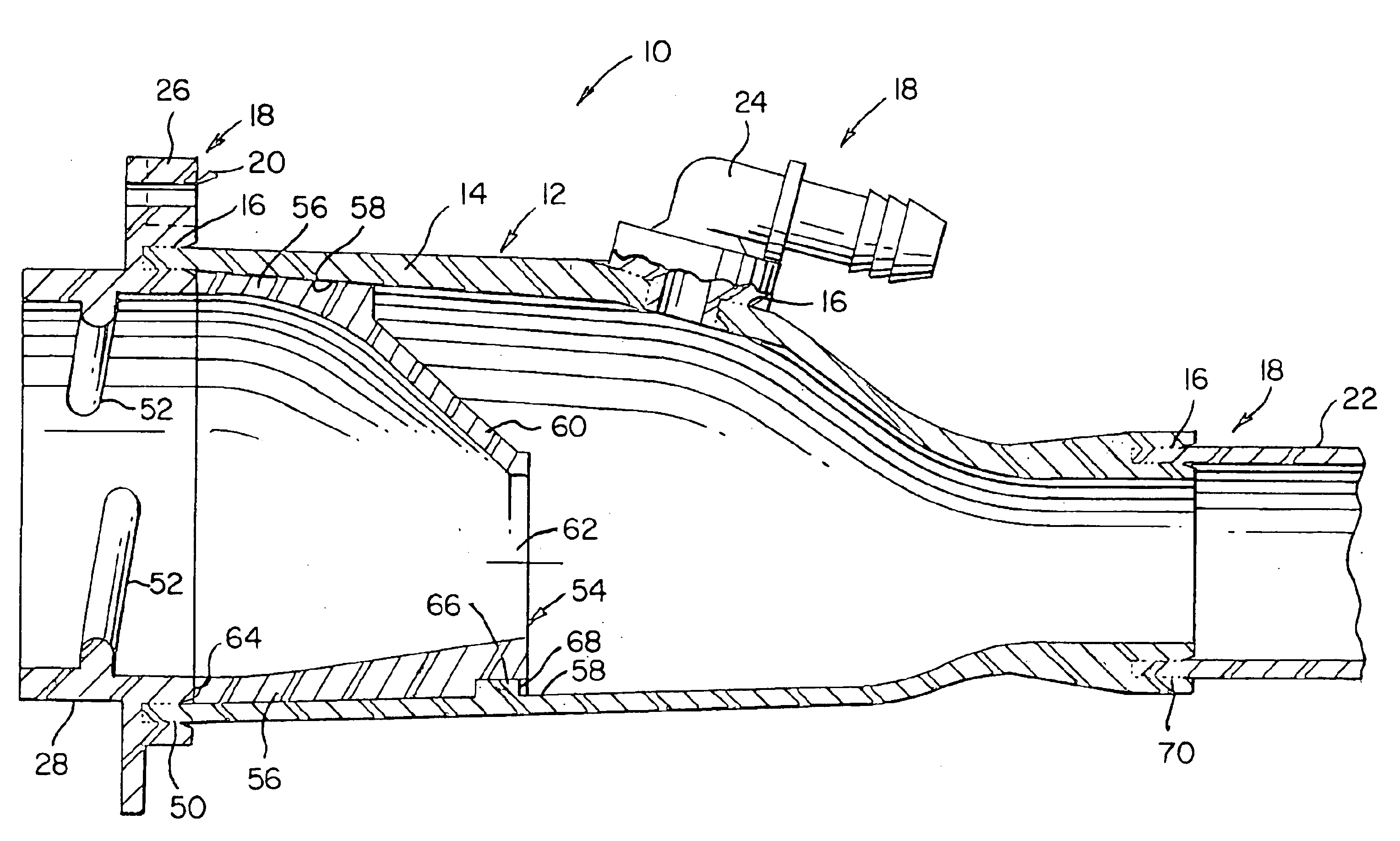
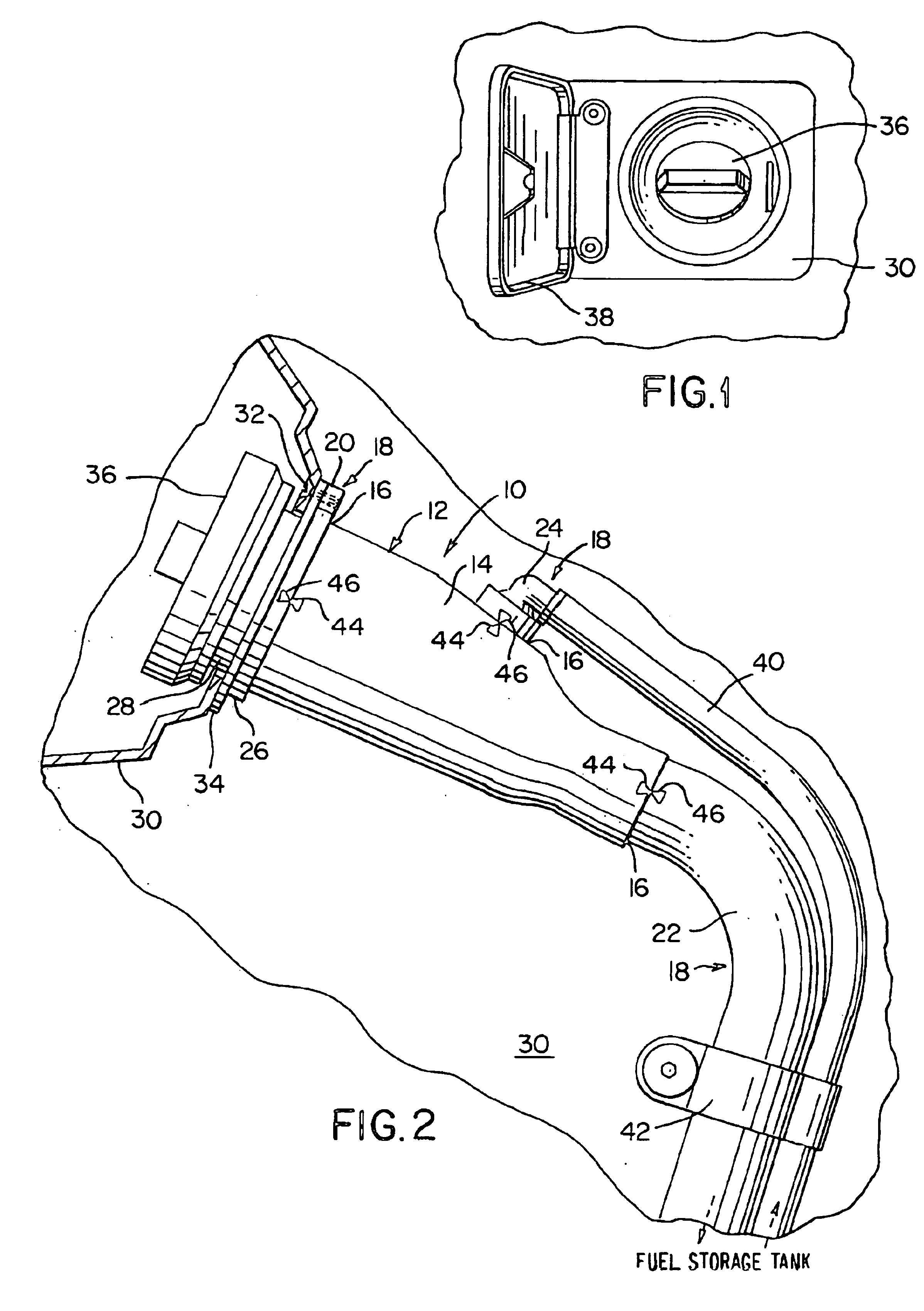
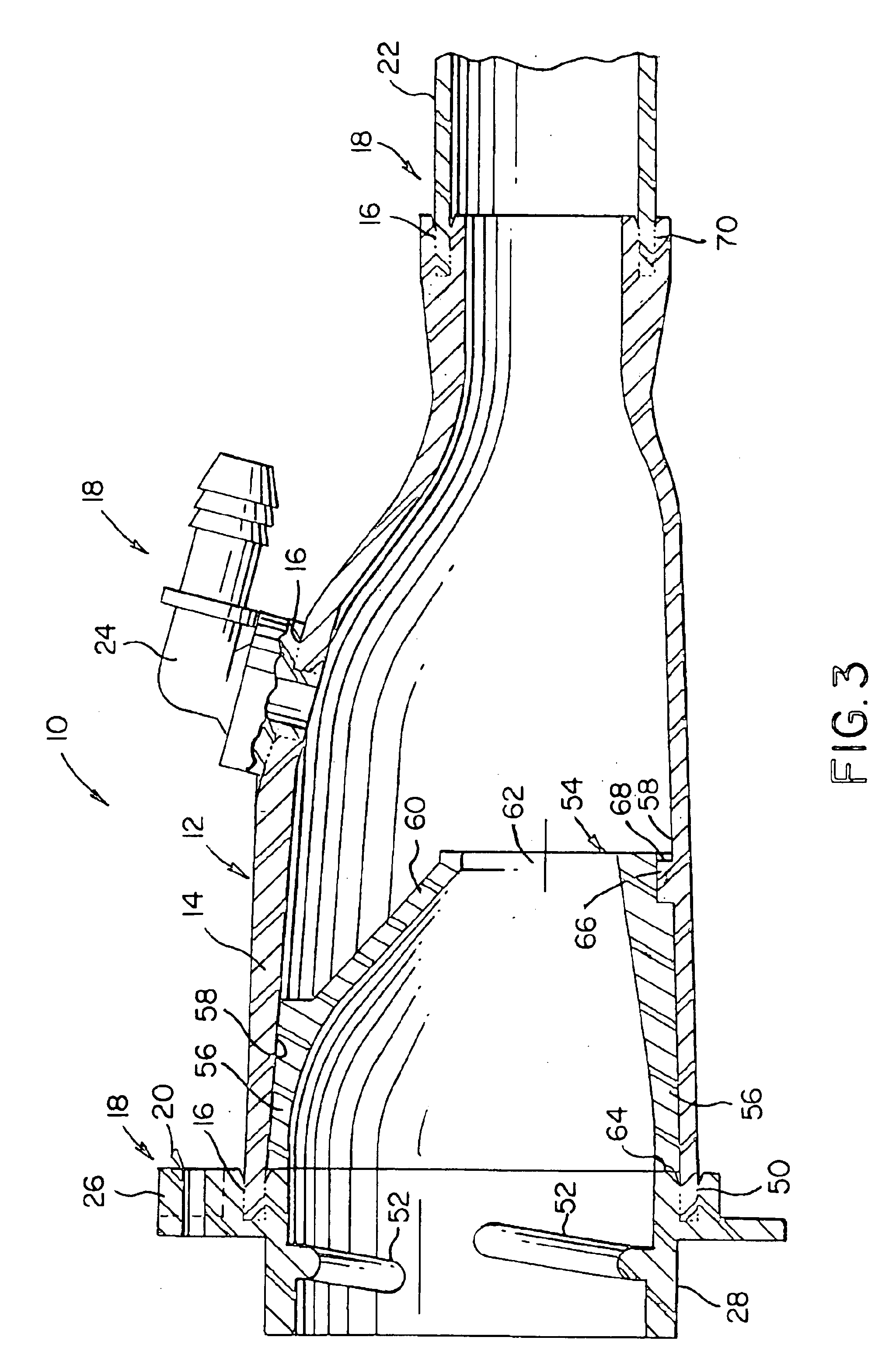
[0030]FIG. 1 is a side elevation view of a portion of a fuel fill system 10 in a motor vehicle such as an automobile, truck, boat, airplane, and the like. The fuel fill system 10 includes a fuel filler neck 12, which includes an outer funnel 14, and one or more components 18 attached to the outer funnel 14 by joints 16 that allow fuel or fuel vapor to be communicated between the outer funnel and the components 18. The one or more components 18 may include a flange 20, a tube 22, and a vapor recirculation fitting 24. The outer funnel 14 and the components 18 are formed from a thermoplastic material, and the joint 16 between each of the components 18 and the outer funnel 14 is formed by welding the component 18 to the outer funnel 14. As will be described in further detail hereinafter, the weld may be formed by spin welding, hot plate welding, laser welding, vibration welding, or ultrasonic welding. Advantageously, the plastic to plastic weld formed between the one or more components ...


PUM

PropertyMeasurementUnit
total thicknessaaaaaaaaaa
included angleaaaaaaaaaa
total thicknessaaaaaaaaaa

Abstract

A fuel fill system includes an outer funnel and one or more components, each formed from a thermoplastic material. The components, which may include a flange, a tube, and a vapor recirculation fitting, are in fluid communication with the outer funnel via welded joints. The welded joints may be formed by at least one of: spin welding, hot plate welding, laser welding, vibration welding, and ultrasonic welding. The plastic to plastic weld provides an electrically conductive, substantially seamless, vapor permeation resistant joint between each of the components and the outer funnel.

Description

BACKGROUND[0001]This invention relates to fuel fill systems in motor vehicles. Fuel fill systems are found in motor vehicles such as automobiles, trucks, boats, airplanes, and the like, and serve to transfer fuel provided by a source external to the vehicle (e.g., a gas pump) to a fuel storage tank located in the vehicle. In general, fuel fill systems include a funnel assembly, called a fuel filler neck, connected to the fuel storage tank by one or more lengths of tube. The fuel filer neck receives fuel delivered from the external fuel source, and the one or more lengths of tube deliver the fuel to the fuel storage tank. A removable cap (e.g., a gas cap) is secured to the fuel filler neck to seal the fuel fill system after the fueling process.[0002]In a typical fuel fill system, each of the one or more tubes are joined to the fuel filler neck by a press-fit joint, which is formed by sliding the tube over a hollow cylindrical projection on the fuel filler neck. The tube is secured in...

Claims


Application Information

Patent Timeline
Patent Type & Authority Patents(United States)
IPC IPC(8): B65B1/04B60K15/04
CPCB29C66/534B29C65/20B29C66/1122B29C66/1142B29C66/12441B29C66/1312B29C66/322B29C66/73116B29C65/0672B29C66/53243B29C66/12469B29C66/12463B29C66/12449B29C65/00B29C65/06B29C65/08B29C65/16B29K2027/12B29K2077/00B29K2101/10B29K2305/00B29L2009/003B60K15/04B29C66/8322B29C66/73921B29C66/71B29C66/61B29C66/72321B29C66/72341B29C66/112B29C66/116B29C66/1222B29C66/1224B29L2031/7172B29K2059/00B29K2023/06
Inventor SWANE, JEFFREY A.
Owner FLUID ROUTING SOLUTIONS
Why Eureka
Try Eureka