Vehicle door latching mechanism having an improved link rod

a technology of latching mechanism and vehicle door, which is applied in the field of latching mechanism, can solve the problems of a number of undesirable situations, a relatively complex mechanism for opening the door of a modern vehicle, and a large number of components, and achieves the effects of improving the safety of passengers

Inactive Publication Date: 2005-04-19
FCA US
View PDF15 Cites 47 Cited by
  • Summary
  • Abstract
  • Description
  • Claims
  • Application Information

AI Technical Summary

Benefits of technology

[0014]One object of the present invention is simplified mechanism to prevent opening of a vehicle door as a result of lateral acceleration.

Problems solved by technology

The mechanism for opening the door on a modern vehicle, however, remains primarily mechanical.
Unfortunately, in an accident involving a lateral impact the outer door handle's inertia keeps it in place, while the force of the impact moves the vehicle.
This creates the potential for a number of undesirable situations during an accident: an occupant of the vehicle could be ejected; the door could open and then close on an occupant's arm or leg; accident debris could be projected into the vehicle interior; etc.
Prior art solutions, particularly those described in described in U.S. Pat. Nos. 3,967,844; 5,669,642; 6,447,030; and 6,464,270 B1 are relatively complex, difficult and expensive to manufacture, more likely to fail, and difficult to maintain and repair.
While the mechanism described in U.S. Pat. No. 5,432,462 appears somewhat efficient at first glance, a careful reading of this reference reveals a number of significant problems.
At best the described designs require complex tuning to achieve operational reliability.
At worst, the described designs do not sufficiently decouple the handle's inertia from the activating arms to prevent a door from opening during lateral impact.

Method used


Image

  • Vehicle door latching mechanism having an improved link rod
  • Vehicle door latching mechanism having an improved link rod
  • Vehicle door latching mechanism having an improved link rod

Examples


Embodiment Construction

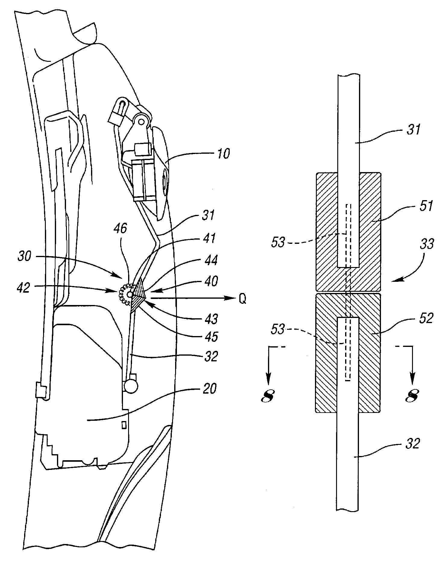
[0028]The present invention provides a simple but elegant solution to the limitations of the prior art as discussed above. The present invention is based on a link rod design that is easy and inexpensive to manufacture, unlikely to fail, and simple to repair and replace if necessary. Such a link rod comprises a first section and a second section joined by a lateral connector.

[0029]As used herein, a lateral connector is a connecting device that permits the fist section and the second section to move laterally while permitting, at most, minimal longitudinal motion of the first and second sections relative to each other.

[0030]If an accident occurs that involves a lateral impact into a door having a door handle, link rod, and latch mechanism according to the present invention, the force generated by the impact acts on the first section and the second section joined by the lateral connector prior to acting on the door handle causing the link rod to buckle at the point where the first se...


PUM


Abstract

A link rod flexibly connecting an exterior door handle of a motor vehicle and a door latching mechanism to prevent actuation of the door latching mechanism as the result of a lateral collision, the link rod comprising: a first section connected to the vehicle door handle; a second section operatively connected to the door latching mechanism; and a lateral connector operatively connecting the first section to the second section. The lateral connector may be a laterally flexible spring, laterally flexible synthetic material, or a hinge point.

Description

FIELD OF THE INVENTION[0001]The present invention relates to a latch mechanism for a vehicle door. More specifically, the present invention describes an improved link rod for connecting the exterior door handle and the door latch mechanism that prevents latch release during lateral impact.BACKGROUND OF THE INVENTION[0002]Early motorized vehicles were little more than horse drawn carriages with a motor replacing the horses. Doors on these early vehicles were simple affairs. A single piece of material, such as wood or metal, was hinged on one side and secured with a simple latch. The mechanism was no more complicated than what currently might be used on a garden gate.[0003]In contrast, modern motorized vehicles are infinitely more sophisticated. Not surprisingly, the doors on modern vehicles have gone well beyond their simple origins. Features like powered windows and locks and their associated controls are now considered standard as are a variety of related safety features.[0004]The ...

Claims


Application Information

Patent Timeline
Patent Type & Authority Patents(United States)
IPC IPC(8): E05B65/20E05B65/12
CPCE05B77/06E05B79/12Y10T74/20006Y10S292/22Y10S292/65Y10T292/1047Y10T292/03
Inventor SCHOEN, ROBERT MROZSA, ISTVANGRATTON, DALE LCARR, DAVID R.
Owner FCA US
Why Eureka
Try Eureka