

Bracket coupling structure
a coupling structure and bracket technology, applied in the direction of coupling device connection, roof, lighting support device, etc., can solve the problems of inability to maintain the bracket b>100/b> in a complete mounting position, become difficult to assemble the bracket, etc., and achieve small rotational resistance and large rotational resistance
- Summary
- Abstract
- Description
- Claims
- Application Information
AI Technical Summary
Benefits of technology
Problems solved by technology
Method used
Image

Examples
Embodiment Construction
[0032]Hereinafter, an embodiment of the present invention is described below with reference to the accompanying drawings.
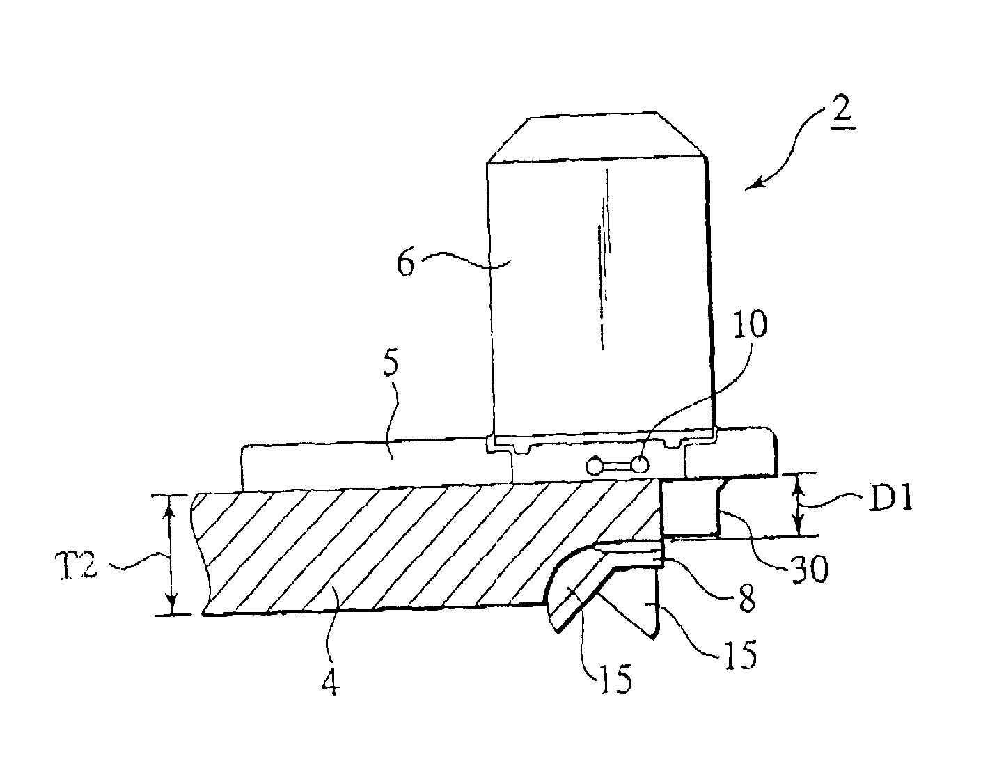
[0033]The presently filed embodiment contemplates to provide a bracket coupling structure of the present invention that is applied to a vehicle-body mounting bracket 1 that allows a sunvisor (auxiliary unit), located on an upper end of a front window for a driver's seat or an assistant driver's seat, to be fixed to a panel that forms a mounting objective plate body.
[0034]As shown in FIG. 4, the vehicle-body mounting bracket 1 is comprised of a panel-side bracket (bracket) 2 adapted to be fixed to a trim (mounting objective plate body) 4 forming interior material of a panel, and a visor-side bracket 3 united to the panel-side bracket 2 and supporting a sunvisor (not shown).
[0035]As shown in FIGS. 5 to 8 in detail, the panel-side bracket 2 is comprised of a thin flat-plate shaped, base plate 5, a panel-side connector section 6 protruding upward from the base plate 5...
PUM
 Abstract
Description
Claims
Application Information