
Ink-jet printhead and method of manufacturing the same

Inactive Publication Date: 2005-04-19
S PRINTING SOLUTION CO LTD
View PDF7 Cites 44 Cited by
  • Summary
  • Abstract
  • Description
  • Claims
  • Application Information

AI Technical Summary

Benefits of technology

[0012]The present invention provides a monolithic ink-jet printhead including a nozzle plate having an excellent hydrophobic property and an improved adhering property with a passage plate.

Problems solved by technology

In this method, due to problems including a structural misalignment, the nozzle plate 3 cannot be attached to the substrate 1 in a form of a wafer and should be attached to each chip separated from the wafer, thereby creating a disadvantage in productivity.
If the hydrophobic property is almost non-existent, that is, if the surface of the nozzle plate has a hydrophile property, some of the ink ejected through the nozzle flows out the surface of the nozzle plate, such that the surface of the nozzle plate is contaminated and a size, a direction, and a speed of the ink droplets ejected are not uniform.
As described above, the nozzle plate formed of the polyimide has the hydrophile property and thus has the above-mentioned problems.
As a result, the coating layer used to form the hydrophobic property increases manufacturing costs.

Method used


Image

  • Ink-jet printhead and method of manufacturing the same
  • Ink-jet printhead and method of manufacturing the same
  • Ink-jet printhead and method of manufacturing the same

Examples


Embodiment Construction

[0030]Reference will now be made in detail to embodiments of the present invention, examples of which are illustrated in the accompanying drawings, wherein like reference numerals refer to the like elements throughout. The embodiments are described in order to explain the present invention by referring to the figures.

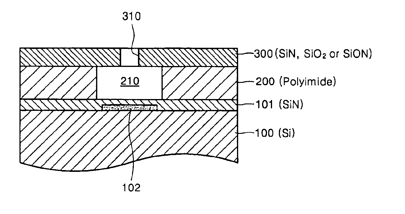
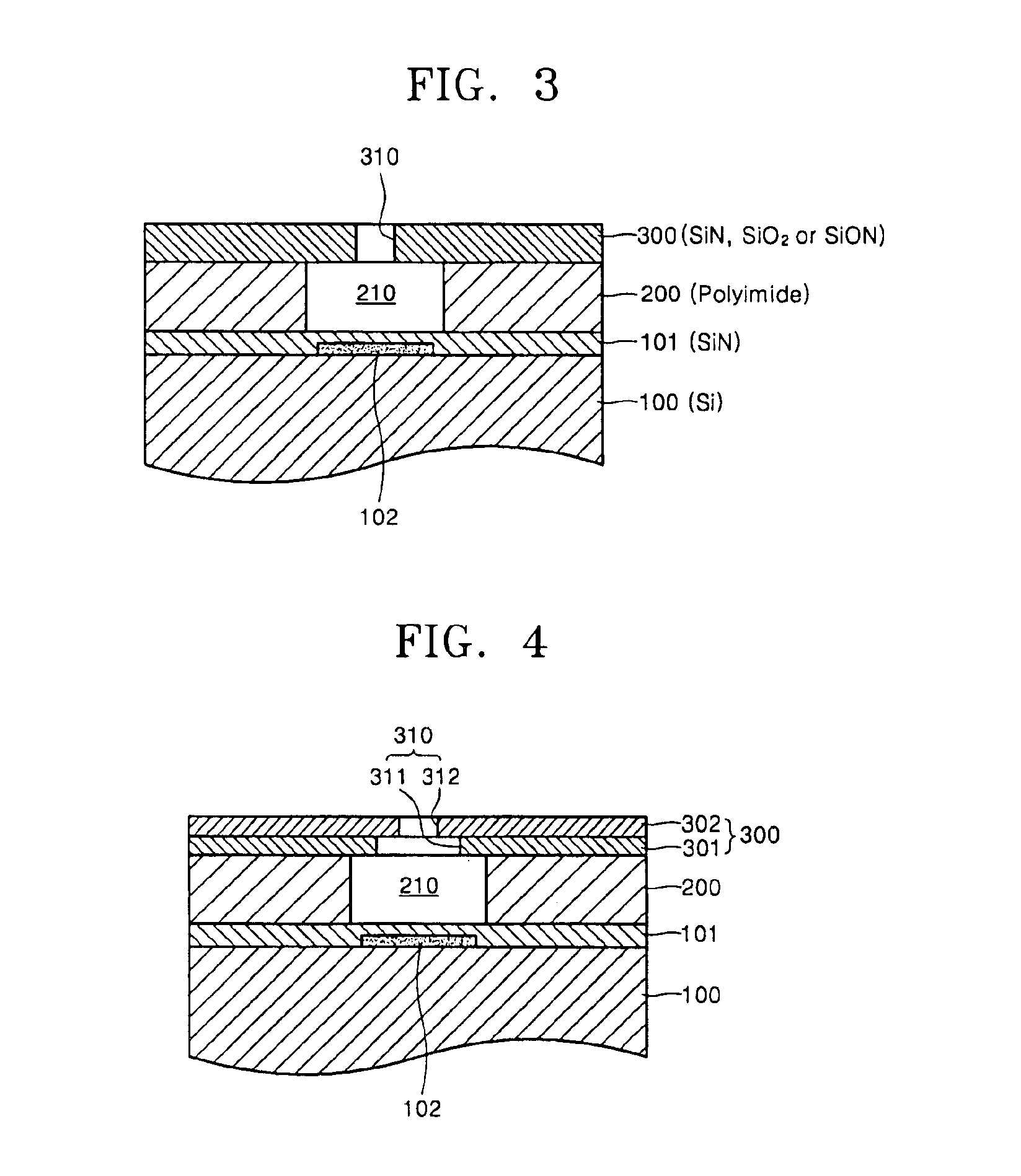
[0031]FIG. 3 is a cross-sectional view schematically illustrating an ink-jet printhead according to an embodiment of the present invention. A heater 102 is formed on a surface of a silicon (Si) substrate 100, and a passivation layer 101 is formed on the substrate 100. The heater 102 is an electric heating apparatus and is connected to a conductor and pads provided on the substrate 100. In FIG. 3, the conductor and pads have not been shown. A passage plate 200 formed of a photoresist, such as polyimide, is placed on the passivation layer 101. The passage plate 200 provides an ink chamber 210 placed above the heater 102 and an ink supply passage (not shown) supplying ink ...


PUM


Abstract

An ink-jet printhead and a method of manufacturing the ink-jet printhead include a substrate on which at least one heater and a passivation layer protecting the at least one heater are formed, a passage plate formed on the substrate to provide a chamber corresponding to the at least one heater, and a nozzle plate in which an orifice corresponding to the chamber is formed. The passage plate is formed of photoresist, and the nozzle plate is formed of a silicon-family material at a temperature limited by characteristics of the passage plate.

Description

CROSS-REFERENCE TO RELATED APPLICATIONS[0001]This application claims the benefit of Korean Patent Application No. 2002-33724, filed Jun. 17, 2002, in the Korean Intellectual Property Office, the disclosure of which is incorporated herein by reference.BACKGROUND OF THE INVENTION[0002]1. Field of the Invention[0003]The present invention relates to an ink-jet printhead and a method of manufacturing the ink-jet printhead, and more particularly, to an ink-jet printhead including a nozzle plate having an excellent hydrophobic property and an excellent adhering property, and a method of manufacturing the ink-jet printhead.[0004]2. Description of the Related Art[0005]In Ink-jet printheads, an electro-thermal transducer (ink jet type) generating bubbles in ink using a heat source and ejecting ink droplets by a force generated by the bubbles is mainly used.[0006]FIG. 1 is a perspective view schematically illustrating a structure of a conventional ink-jet printhead, and FIG. 2 is a cross-secti...

Claims


Application Information

Patent Timeline
IPC IPC(8): B41J2/16B41J2/235B41J2/05
CPCB41J2/1603B41J2/1628B41J2/1642B41J2/1631B41J2/1639B41J2/1629B41J2/235
Inventor KIM, YUN-GI
Owner S PRINTING SOLUTION CO LTD
Learn More