Methods and systems for projecting images at greater than 180 degrees

Inactive Publication Date: 2005-04-19
BARCO NV +2
View PDF8 Cites 25 Cited by
  • Summary
  • Abstract
  • Description
  • Claims
  • Application Information

AI Technical Summary

Benefits of technology

[0009]To provide an immersive effect, for example, other embodiments of the present invention may comprise two image sources that are configured to generate first and second arrays of image pixels and two lens assemblies that are configured to respectively project the first and second arrays of image pixels at projection angles that are greater than 180° onto a surface in opposite directions of each other. The combination of the first and second arrays of image pixels may cover a continuous, 360° portion of the hemispherical surface.

Problems solved by technology

These systems, however, may require significant alignment and upkeep, including edge blending and color matching.
They also may be expensive and may require a room that is on average twice as big as the display surface.
Multi-projector front projection environments typically do not require the extra room of rear projection environments, but generally can not achieve the same level of immersion and still may suffer the same cost and alignment problems.
Single projector, front projection environments may be lower cost and may also be more readily aligned, but these systems may not provide the user with greater with a 170° field of view (FOV) because the viewer may need to be located behind the projector.

Method used


Image

  • Methods and systems for projecting images at greater than 180 degrees
  • Methods and systems for projecting images at greater than 180 degrees
  • Methods and systems for projecting images at greater than 180 degrees

Examples


Embodiment Construction

[0017]While the invention is susceptible to various modifications and alternative forms, specific embodiments thereof are shown by way of example in the drawings and will herein be described in detail. It should be understood, however, that there is no intent to limit the invention to the particular forms disclosed, but on the contrary, the invention is to cover all modifications, equivalents, and alternatives falling within the spirit and scope of the invention as defined by the claims. Like reference numbers signify like elements throughout the description of the figures.

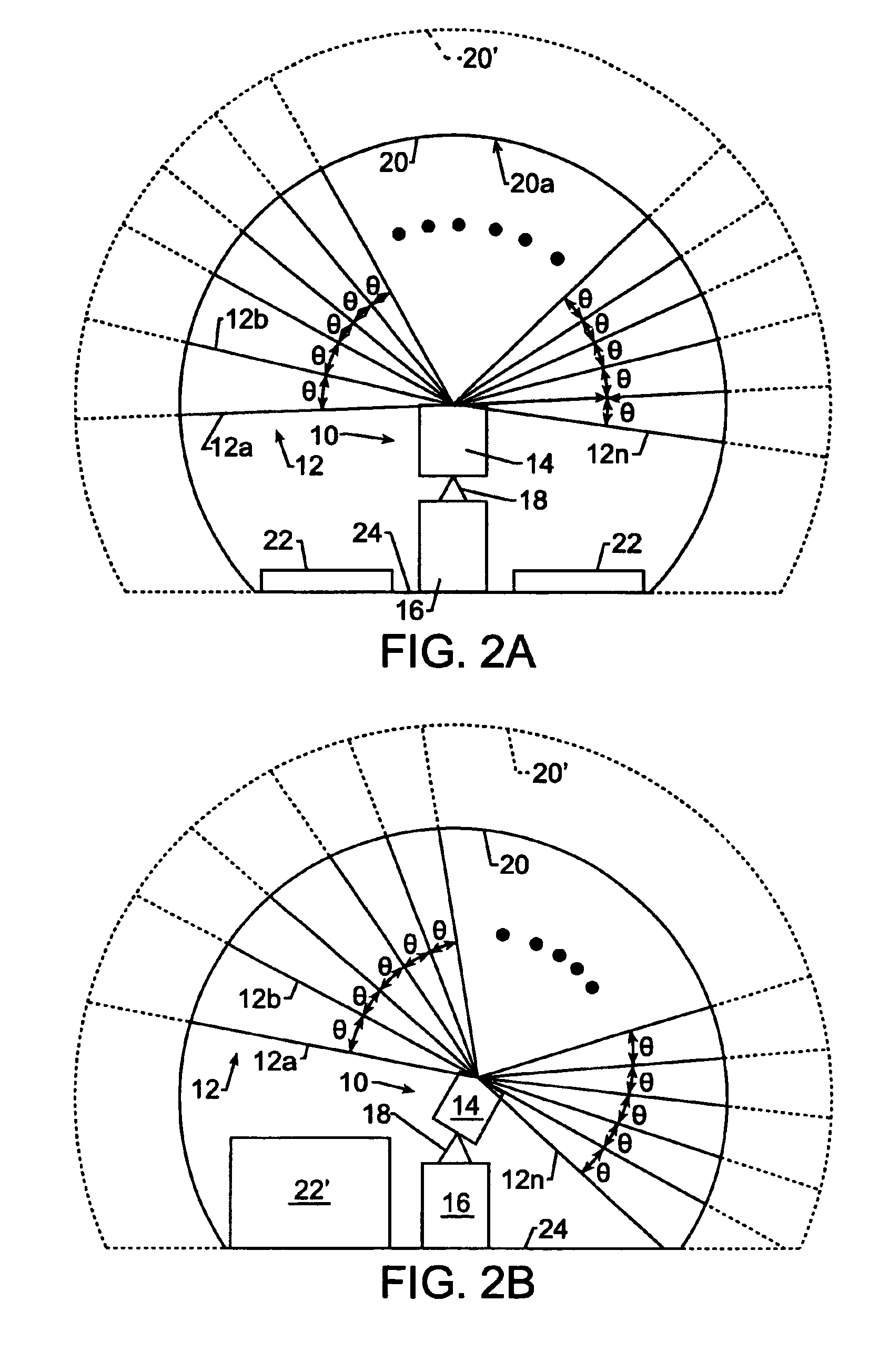
[0018]Referring now to FIGS. 2A and 2B, a tiltable optical projection system having constant angular separation of projected pixels, according to some embodiments of the present invention, will now be described. An optical projection system 10 projects an array of image pixels 12 having constant angular separation among adjacent pixels as indicated by the angle θ, which is constant among adjacent pixels 12a-12n. M...


PUM


Abstract

An optical projection system includes an image source that is configured to generate an array of image pixels. A lens assembly is configured to project the array of image pixels onto a hemispherical surface at a projection angle greater than 180°. The lens assembly may include a wide-angle lens assembly and an image relay lens assembly that is configured to reduce dispersion in the array of image pixels between the image source and the wide-angle lens assembly. The wide-angle lens assembly may include a meniscus lens assembly and a wavefront shaping lens assembly. The lens assembly may be further configured to project the array of image pixels onto the hemispherical surface such that there is a constant angular separation between adjacent image pixels. An optical projection system may also include two image sources that are configured to generate first and second arrays of image pixels and two lens assemblies that are configured to respectively project the first and second arrays of image pixels at projection angles that are greater than 180° onto a surface in opposite directions of each other. The combination of the first and second arrays of image pixels may cover a continuous, 360° portion of the hemispherical surface.

Description

CROSS-REFERENCE TO PROVISIONAL APPLICATION[0001]This application claims the benefit of Provisional Application Ser. No. 60 / 279,912, filed Mar. 29, 2001, entitled Methods and Systems for Projecting Images at Greater than 180 Degrees, the disclosure of which is hereby incorporated herein by reference.BACKGROUND OF THE INVENTION[0002]The present invention relates to optical projection systems and methods, and, more particularly, to hemispherical optical projection systems and methods.[0003]Immersive virtual environments have many applications in such fields as simulation, visualization, and space design. A goal of many of these systems is to provide the viewer with a full sphere (180°×360°) of image. In achieving this goal, there is traditionally a trade-off between complexity and cost. Fully immersive systems using rear projection typically use multiple projections placed around the display surface. These systems, however, may require significant alignment and upkeep, including edge b...

Claims


Application Information

Patent Timeline
IPC IPC(8): G02B27/18G02B13/16G02F1/13G03B21/00
CPCG02B27/18G02B27/02G03B21/142H04N9/3182
Inventor COLUCCI, D'NARDOIDASZAK, RAYMOND L.ZOBEL, JR., RICHARD W.BALU, SURESHMCCONVILLE, DAVID
Owner BARCO NV
Why Eureka
Try Eureka