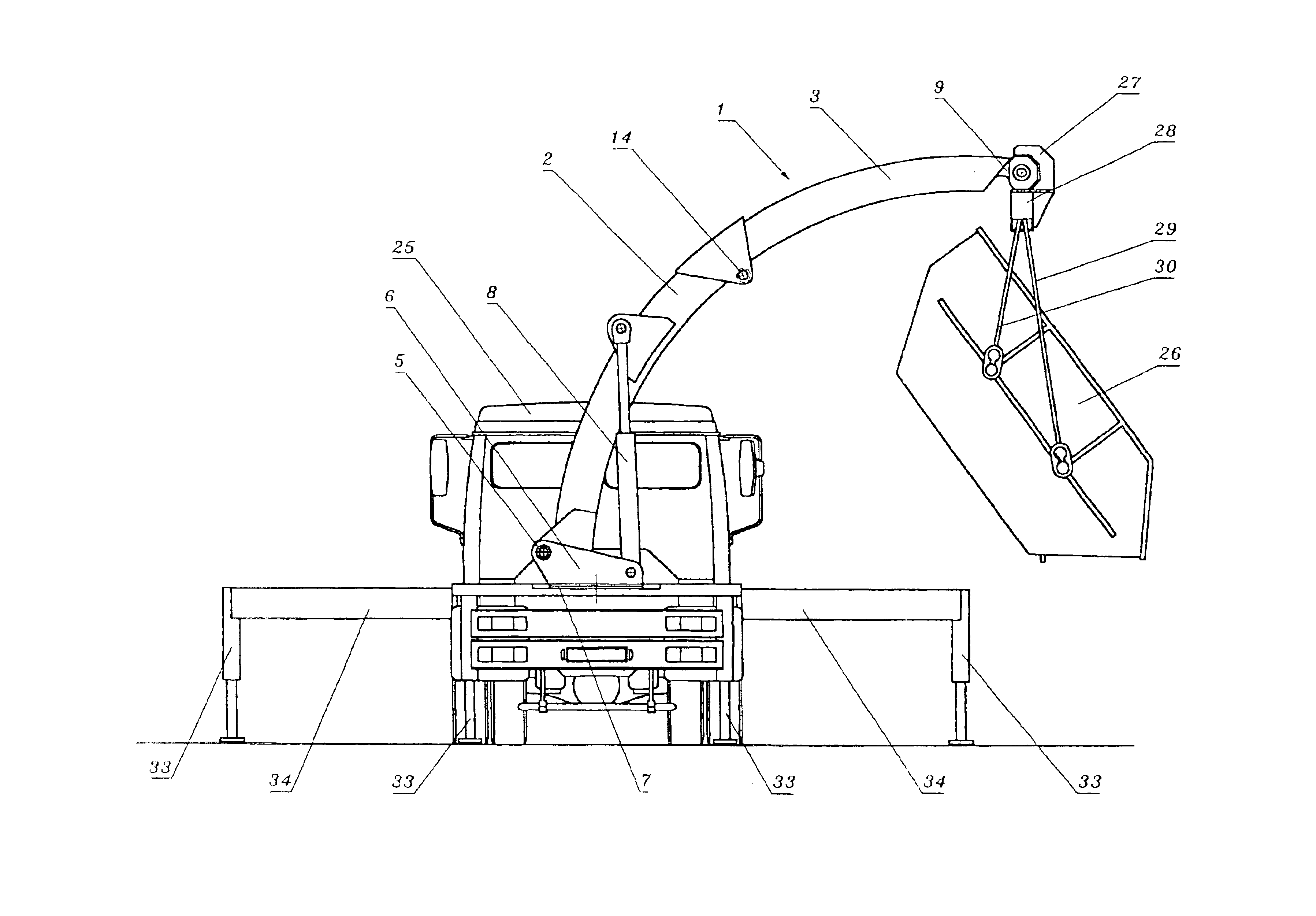
[0006]The object of the invention is to arrange a telescopic boom for a vehicle or a hoist of the type described at the outset such that places can be reached with the telescopic boom, between which and the storage rack there is no free linear passage, without having to fall back on an additional articulated partitioning of the boom.
[0008]Since, as a result of these measures, the box girders are pushed towards one another along a curved path, free linear passage for the telescopic boom is no longer required, which considerably expands the area of application of telescopic boom according to the present invention as compared to conventional telescopic booms. The horizontal components of the extension movement by box girders formed in an arc of a circle becomes overproportionally greater with increasing extension length, in particular with steeper set angles of the telescopic boom, such that such telescopic booms are particularly suitable for reaching spaces which are accessible overhead via a lateral opening.
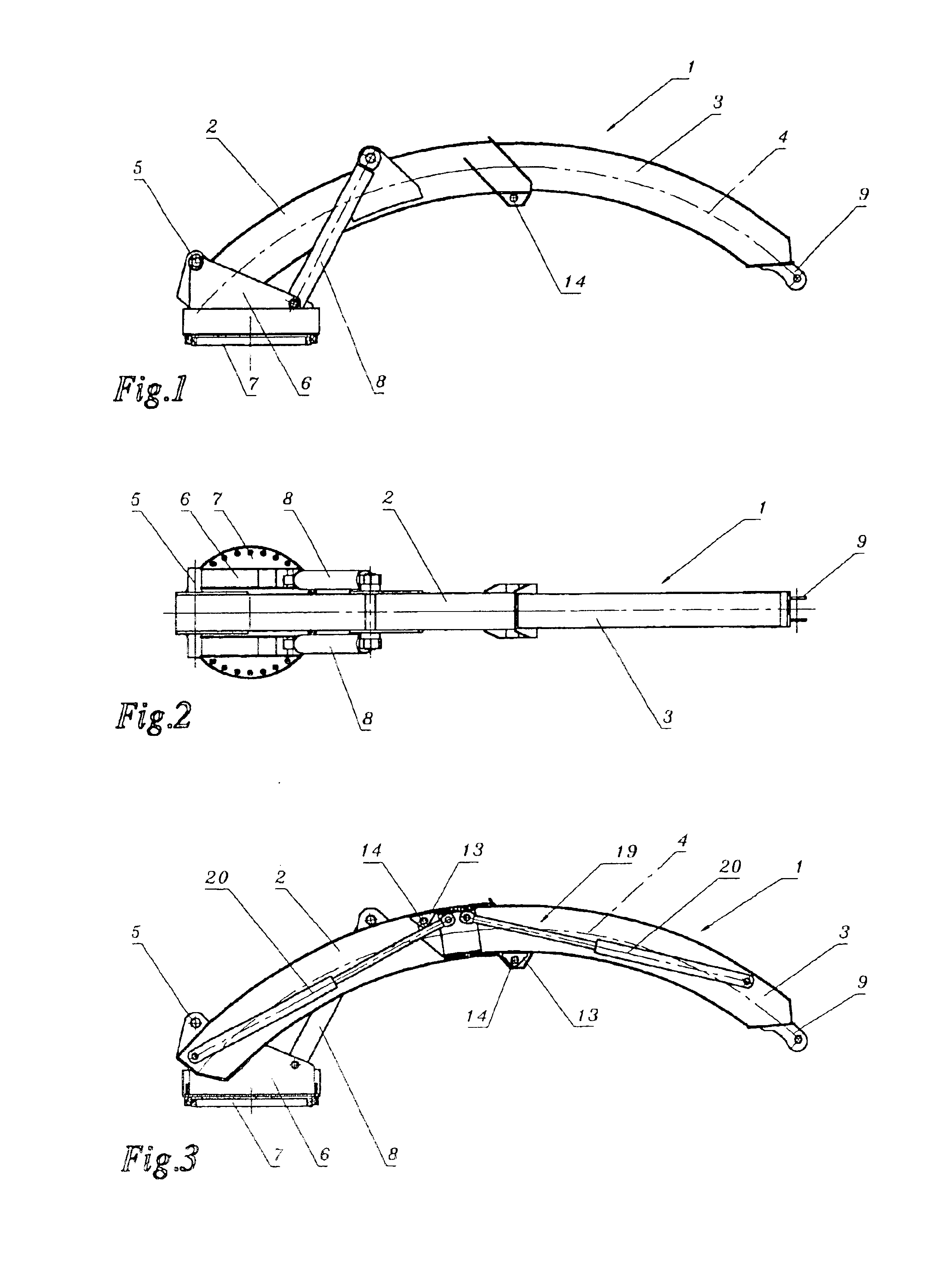
[0010]Whereas mutual adjustment of the intermeshing box girders produces no difficulties with use of a cylindrical
pinion in the case of straight telescopic booms, the arrangement of a cylindrical
pinion inside the box girders in the case of box girders curved to an arc of a circle requires special measures, since by means of a linear extending ram the curved form of the box girders cannot be considered. For this reason the cylindrical
pinion may comprise two rams which are on the one hand articulated to one of the outer girder ends and on the other hand to a common slider mounted displaceably inside the
box girder, such that the rams form a progression adapted to the circular arc shape, in such a way that the rams extend chord-like inside the box girders in linear fashion. The slider mounted displaceably inside the inner
box girder between both rams enables simple mutual displacement of the box girders with simultaneous removal of the radial components of the controlling torque on the box girders. A
servo-drive is also proposed for mutual displacement of the box girders however, comprising at least one rack running along a
box girder and one driving pinion of the other box girder meshing with the rack, so that the box girder connected to the driving pinion is driven along the other box girder with the drive of the driving pinion.
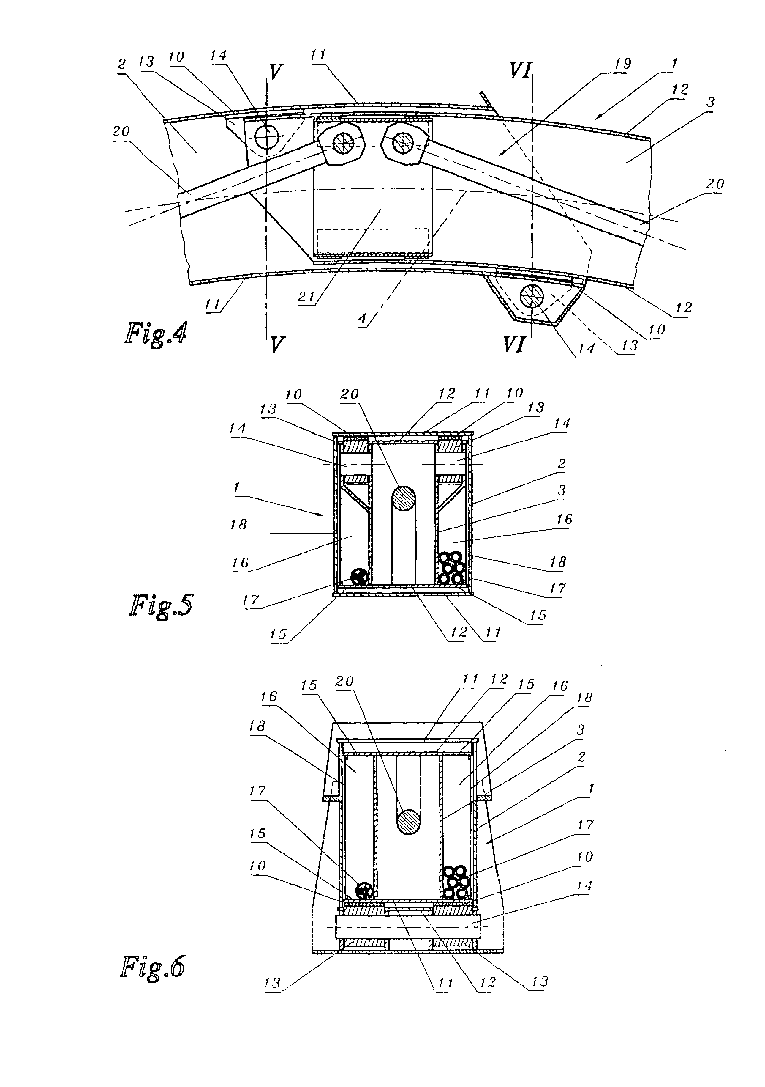
[0011]It is evident that the arc-shaped box girders according to the present invention can also be employed to accommodate supply lines, if the upper and the lower cylindrical wall of the inner box girder form, in a manner known per se, longitudinal edge frames projecting laterally over the box profile and guided on the outer box girder, between which longitudinal channels for taking up these supply lines are formed on the outer sides of the box profile of the inner box girder. These supply lines can serve various purposes, according to the use of the telescopic boom. Accordingly, when telescopic booms according to the present invention are used for fire engines, guide hoses for extinguishers can be laid in these longitudinal channels next to the supply lines for the equipment taken up by the telescopic boom. If supply lines of a larger
diameter are required, as is the case for supplying fresh concrete or
mortar for example, the box profile of the inner box girder can also be employed as a supply line, so that the cross-section of the box girders does not have to be enlarged. In this case, however, the servo-drive cannot be arranged inside the box profile. For this reason the servo-drive may comprise a rack-and-pinion gear, such that the rack of the servo-drive is to be provided in at least one of the longitudinal channels resulting between the longitudinal edge frames outside the box profiles on both sides of the inner box girder, so that the box profile is free for supply.
[0012]To further expand the reach of the telescopic boom the box girder forming the overhanging boom end can bear a boom arm pivoting about a horizontal pivot axis and possibly extending telescopically, which considerably increases the reach of the telescopic boom in cooperation with the circular arc of the telescopic boom on account of its pivoted configuration; this is of particular significance for telescopic booms which are used with feed pipes for different goods, e.g. liquids, liquid-
solid mixtures or pourable goods.
[0014]As already pointed out, telescopic booms according to the present invention can be used in
multiple applications. Inter alia it is possible to utilise the box girders not only for guiding supply lines, but also to design them as accessible and / or navigable tunnel. These correspondingly large-sized box girders can advantageously facilitate connecting an aircraft exit hatch to the ground, with the added
advantage that, despite different exit hatch paths, the connection end of the telescopic boom on the aircraft runs approximately horizontally, before the tunnel floor gradually inclines downwards to overcome the height. The circumstances by which the telescopic boom can be joined to an opening at a distance above an accessible surface with minimal inclination, makes telescopic booms with box girders forming a tunnel also suitable for creating emergency and escape routes, particularly as these emergency and escape routes are protected at least partially from outside influences by the box girders enclosing them.

