Progressive cavity pump/motor

a technology of progressive cavity and power section, which is applied in the direction of machines/engines, rotary/oscillating piston pump components, liquid fuel engines, etc., can solve the problems of large amount of heat, significant deflection and stress in the elastomer, and introduce weaknesses into the operation and life of the pump/motor, etc., to achieve accurate verification of the lead

Inactive Publication Date: 2005-04-19
ROBBINS & MYERS ENERGY SYST
View PDF19 Cites 64 Cited by
  • Summary
  • Abstract
  • Description
  • Claims
  • Application Information

AI Technical Summary

Benefits of technology

[0014]A stator alignment feature is also disclosed, along with tooling which may be used during alignment and positioning to manufacture and repair the stator. Tooling may also be used to accurately verify the lead of any interior profiled stator tube.

Problems solved by technology

The resilient material used for the stator introduces weaknesses into the operation and life of the pump / motor.
Mechanical resistance of the elastomer is also of concern since high pressures are generated in the cavities of the pump / motor.
These high fluid pressures and the necessary reactive forces result in significant deflection and stress in the elastomer, particularly along the rotor / stator interferences.
These forces create friction which generates a large amount of heat during operation, and this heat may be very deleterious to the desired characteristics of the elastomer, and thus deleterious to the performance and life of the pump / motor.
If the heat resulting from the previously mentioned sources becomes excessive, the properties of the elastomer will more generally degrade.
Additionally, the high pressure experienced during operation may deflect the thicker sections of elastomer to the extent that the interference is overcome and contact with the rotor is lost.
This loss of contact results in decreasing speeds for the motor and decreasing flows for the pump, resulting in poor efficiency.
In addition, heat from the pump / motor operation, in some cases in conjunction with the environment in which pump / motor operates, distorts the shape of the elastomer molded to the interior of the metal tube.
As a result of the varying thicknesses and the relatively high thermal expansion of the elastomer, the radially thick sections distort more than the thinner sections of the stator, which results in a geometrical profile drastically different than intended, thereby hindering the proper operation of the pump / motor.
This distorted profile may generate additional heat and further distort the stator profile, creating a system which rapidly contributes to its own degradation and ultimate failure.
During operation, a conventional downhole progressive cavity drill motor develops a great deal of heat due to the friction between the rotor and the stator.
The center of the stator profile lobes is subjected to heat from a large percentage of its surrounding area and is the most limited in transferring this heat to the metal tube due to the thickness of the elastomeric material.
With extended operation, the center of the stator profile lobes may become hard and brittle as a result of the excessive heat in this area, and the mechanical properties of the rubber or elastomer in this area are accordingly severely degraded.
As a result, the stator lobe may break or “chunk out” of the stator profile.
In addition, the pressure acting in the chambers between the stator and the rotor may exceed the strength of the elastomeric material, and the stator lobe may deflect from its original shape or may break or “chunk off” the stator lobe.

Method used


Image

  • Progressive cavity pump/motor
  • Progressive cavity pump/motor
  • Progressive cavity pump/motor

Examples


Embodiment Construction

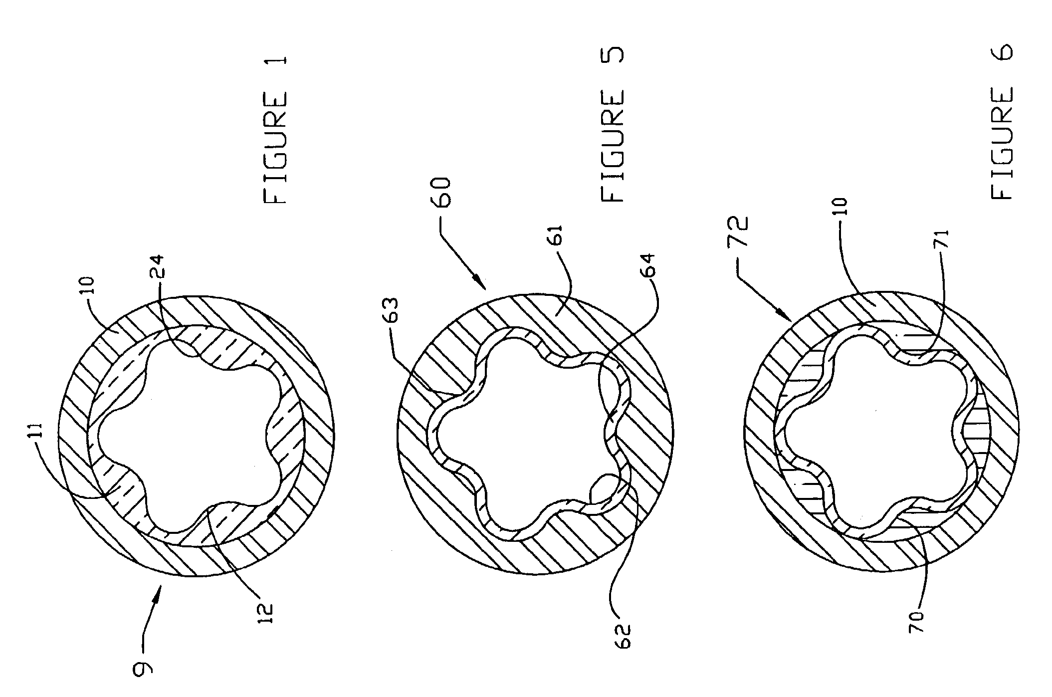
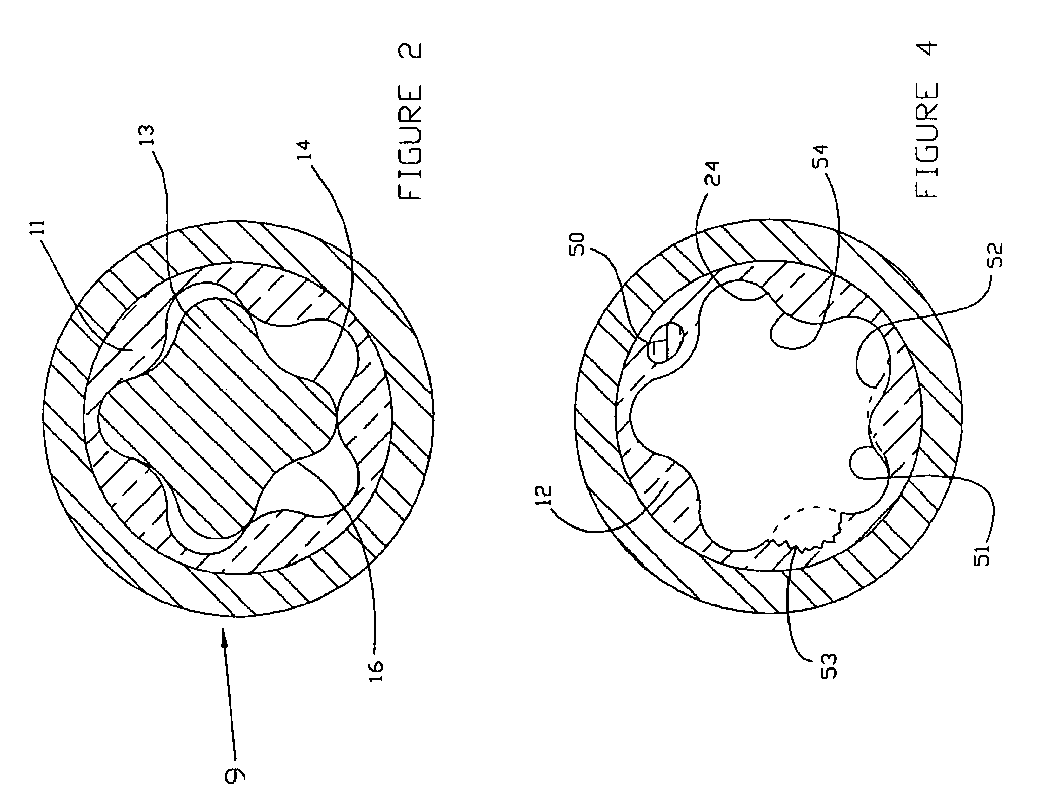
[0030]FIG. 1 depicts a conventional progressive cavity stator 9 of a pump or motor which includes a steel or similar structural material tube or housing 10. Elastomeric layer 11 is molded into the tube 10. The number of lobes 12 may be of any practical number greater than one. As can be seen in FIG. 2, the rotor 13 has one less lobe 14 than the mating stator. The number of lobes depends on the desired operating characteristics of the pump or motor. As the rotor 13 rotates inside of the stator 9, debris entrained in the fluid which supplies the energy for a motor, or is being moved by a pump, may become caught between the rotor surface 16 and the stator surface 24. The flexible nature of an elastomeric material allows this debris to be pressed into the stator surface 24, thereby allowing the rotor 13 to continue rotating unabated.

[0031]FIG. 3 illustrates a conventional technology progressive cavity motor 18, which alternatively could be a progressive cavity pump. To transmit the powe...


PUM


Abstract

A progressive cavity pump or motor, particularly suitable for hydrocarbon recovery operations, includes a rotor 20 and a stator 10. Fluid pressure in cavities between the stator and the rotor create torque which rotates the bit. An interior surface of the stator is rigidly secured to the outer housing of the pump stator and defines an interior profile. A substantially uniform thickness elastomeric layer 62 is supported on the outer housing. The pump rotor has an exterior profile which corresponds with the interior profile of the elastomeric layer.

Description

FIELD OF THE INVENTION[0001]This invention relates to the design and manufacture of pumps and motors utilizing progressive cavity power sections. More specifically, this invention relates to the design and manufacture of the female stator component of the progressive cavity pump or motor.BACKGROUND OF THE INVENTION[0002]U.S. Pat. No. 1,892,217 discloses a gear mechanism of a progressive cavity pump or motor. This progressive cavity technology is commonly used in a pump to convert mechanical to power fluid energy, and in a motor to convert fluid energy to mechanical power. As a downhole motor, the moving energy of a drilling fluid may be converted to rotary motion to rotate a bit to drill a subterranean well. Other publications of interest including U.S. Pat. Nos. 3,084,631; 4,104,009; 4,676,725; 5,171,138; 5,759,019; 6,183,226; 6,309,195; and 6,336,796; and WO 01 / 44615.[0003]Operation of a progressive cavity pump or motor utilizes an interference between the external profile of the ...

Claims


Application Information

Patent Timeline
Patent Type & Authority Patents(United States)
IPC IPC(8): F04C2/00F04C2/107
CPCF04C2/1073F04C2/1075F04C2230/00
Inventor ZITKA, MARK D.MURRAY, WILLIAM D.
Owner ROBBINS & MYERS ENERGY SYST
Why Eureka
Try Eureka