LGA connector and terminal thereof

Active Publication Date: 2005-04-19
MOLEX INC
View PDF6 Cites 59 Cited by
  • Summary
  • Abstract
  • Description
  • Claims
  • Application Information

AI Technical Summary

Benefits of technology

[0009]An object of the present invention is to provide an electronic connector and a terminal structure

Problems solved by technology

1. Dispersing pressing forces to make the pressing forces as small as possible, otherwise, the pressing forces is liable to make the terminal deformed. Furthermore, it causes the terminal unable to be secured in a corresponding inserting slot.
2. Improving the mounting sta

Method used


Image

  • LGA connector and terminal thereof
  • LGA connector and terminal thereof
  • LGA connector and terminal thereof

Examples


Embodiment Construction

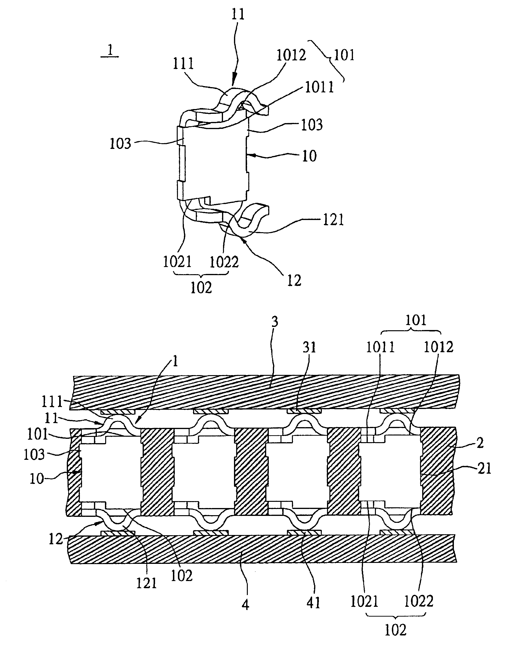
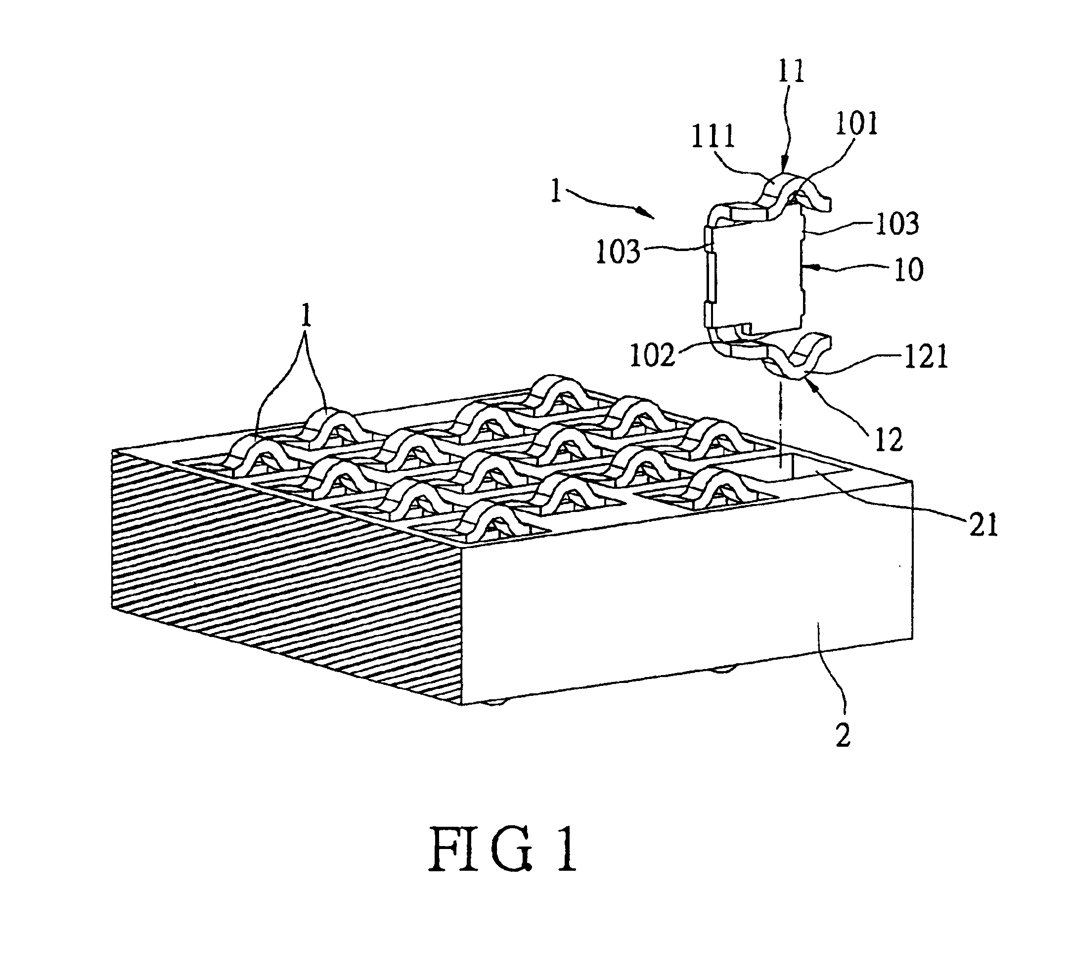
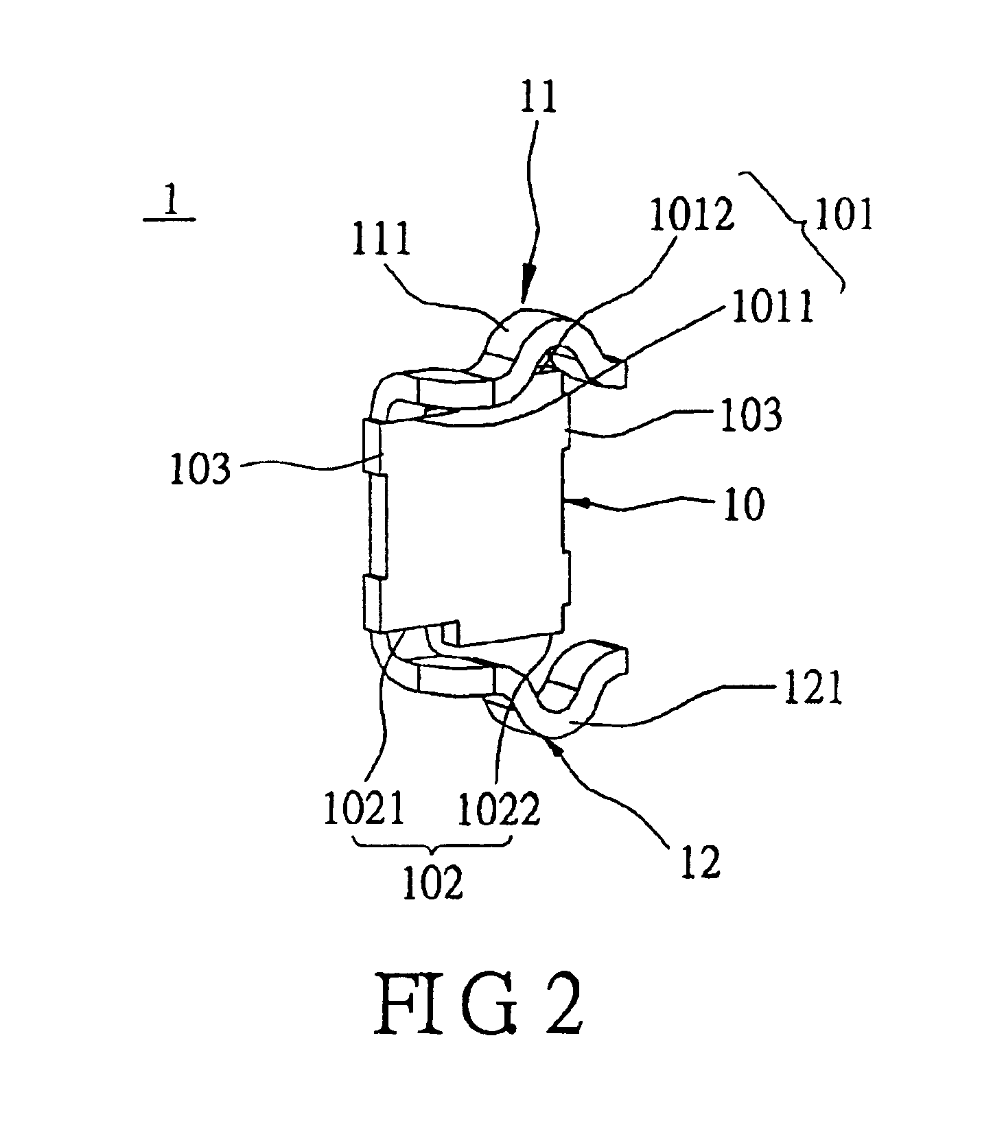
[0017]FIGS. 1 and 2 show an electronic connector and a terminal structure thereof. The electronic connector comprises an insulative housing 2 and a plurality of terminals 1. The insulative housing 2 includes a plurality of terminal slots 21, and each of the plurality of terminals 1 is respectively receipted in the corresponding terminal slots 21.

[0018]Each of the plurality of terminal 1 comprises a base 10, a first elastic arm 11 and a second elastic arm 12. The base 10 includes four sides: a top side 101, a bottom side 102, a right side (not labeled) and a left side (not labeled). The top side 101 has a first end 1011 and a second end 1012. The bottom side 102 has a first end 1021 and a second end 1022. The first elastic arm 11 frontward extends from the first end 1011 of the top side 101 and further laterally extends toward the second end 1012 of the top side 101 in a horizontal direction parallel to the top side 101. The second elastic arm 12 frontward extends from the first end ...


PUM


Abstract

An electronic connector includes an insulative housing having a plurality of terminal slots and a plurality of terminals received in the corresponding terminal slots. Each of the terminals includes a base having a top side and a bottom side, and both of the top side and the bottom side have a first end and a second end. A first elastic arm frontward extends from the first end of the top side and further laterally extends in a horizontal direction parallel to the top side toward the second end of the top side. A second elastic arm frontward extends from the first end of the bottom side and further laterally extends in a horizontal direction parallel to the bottom side toward the second end of the bottom side. The electronic connector of the present invention can effectively disperse pressing forces and improve an inserted stability of the terminal.

Description

BACKGROUND OF THE INVENTION[0001]1. Field of the Invention[0002]The present invention relates to an electronic connector and its terminal, especially to an electronic connector and terminal thereof used in LGA packaging.[0003]2. Description of Prior Art[0004]LGA (Land Grid Array) is one of most common package for IC (Integrated circuit) or wafer. A LGA connector provides a solderless interconnection with a target PCB (Printed Circuit Board). Such an electronic connector adapted to a LGA package generally comprises an insulative housing, wherein has a plurality of cutouts, in which a plurality terminals are mounted respectively. Each terminal has a pair of electronic contacts for electrically connecting with a CPU (Central Processing Central) and a PCB respectively. And, both of a bottom surface of the CPU and an upper surface of the PCB are respectively provided a plurality of pads to implement electronic interconnection with the electronic contacts of the terminal without solder.[0...

Claims


Application Information

Patent Timeline
IPC IPC(8): H01R13/24H01R13/22H01R12/04
CPCH01R12/714H01R13/2435
Inventor CHIANG, CHUN-HSIANG
Owner MOLEX INC
Why Eureka
Try Eureka