Bias circuit linearization and dynamic power control

a technology of bias circuits and linear circuits, applied in the direction of gain control, pulse automatic control, amplifier modification to reduce non-linear distortion, etc., can solve the problems of linear system design placing significant constraints on individual circuits within the system, the efficiency of the amplifier circuit is greatly reduced, and the system utilizing conventional power amplifiers normally operate at less than peak efficiency for a substantial portion of the tim

Inactive Publication Date: 2005-04-19
SKYWORKS SOLUTIONS INC
View PDF13 Cites 42 Cited by
  • Summary
  • Abstract
  • Description
  • Claims
  • Application Information

AI Technical Summary

Problems solved by technology

Today, one problem with operating a power amplifier at low distortion levels is that the efficiency of the amplifier circuit is greatly reduced because it is not amplifying at its highest capability.
However, in order to accommodate the linearity of today's devices with communication signals having varying amplitudes (e.g. cellular telephones), systems utilizing conventional power amplifiers normally operate at less than peak efficiency for a substantial portion of the time.
Of course, in today's market, wireless communications devices, such as cellular telephones, must consistently provide clear and undistorted transmissions.
In most cases, linear system design places significant constraints on individual circuits within the system.
Essentially, the individual circuits must be designed with a large dynamic range, which makes the circuits inefficient and expensive.
Techniques that implement feedback, predistortion, feedforward, and other signal processing concepts are not feasible for use in RFIC designs.

Method used


Image

  • Bias circuit linearization and dynamic power control
  • Bias circuit linearization and dynamic power control
  • Bias circuit linearization and dynamic power control

Examples


Embodiment Construction

[0021]Among those benefits and improvements that have been disclosed, other objects and advantages of this invention will become apparent from the following description taken in conjunction with the accompanying drawings. The drawings constitute a part of this specification and include exemplary embodiments of the present invention and illustrate various objects and features thereof.

[0022]Throughout this description, the embodiments and examples shown should be considered as exemplars, rather than limitations, of the present circuit. Of course, these embodiments and examples are not intended to be limiting and other embodiments may be implemented.

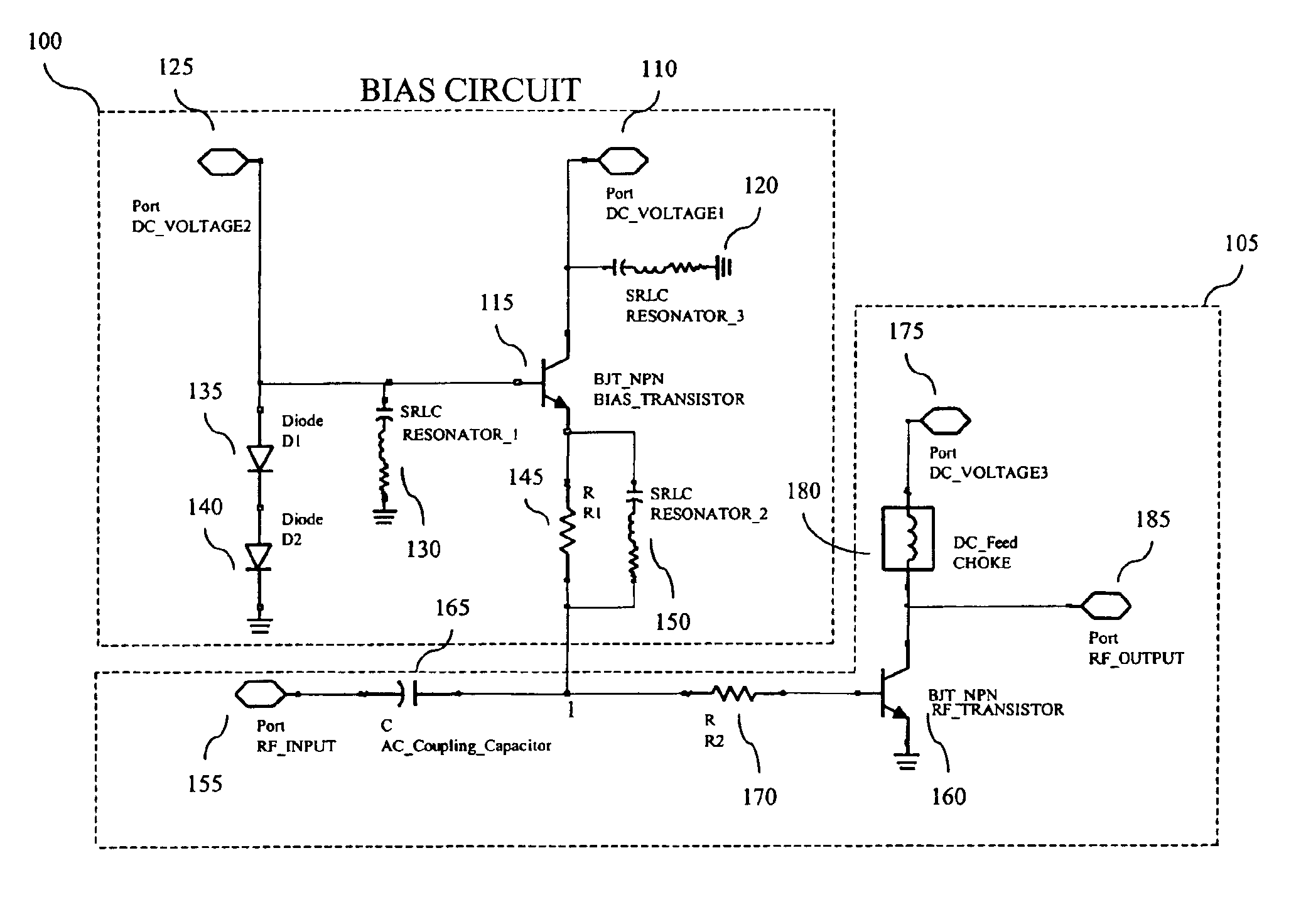
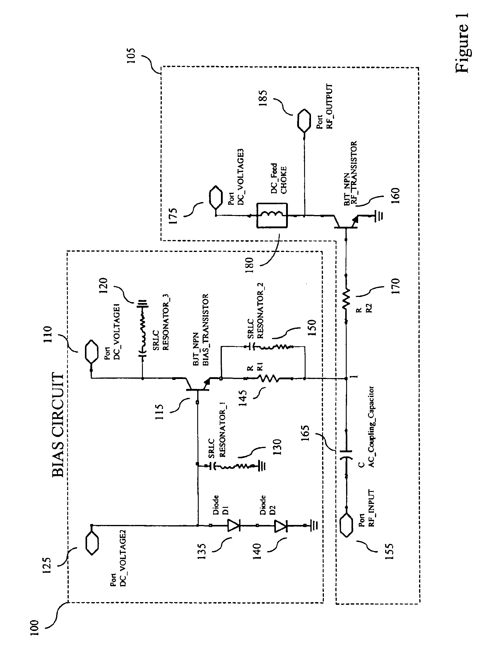
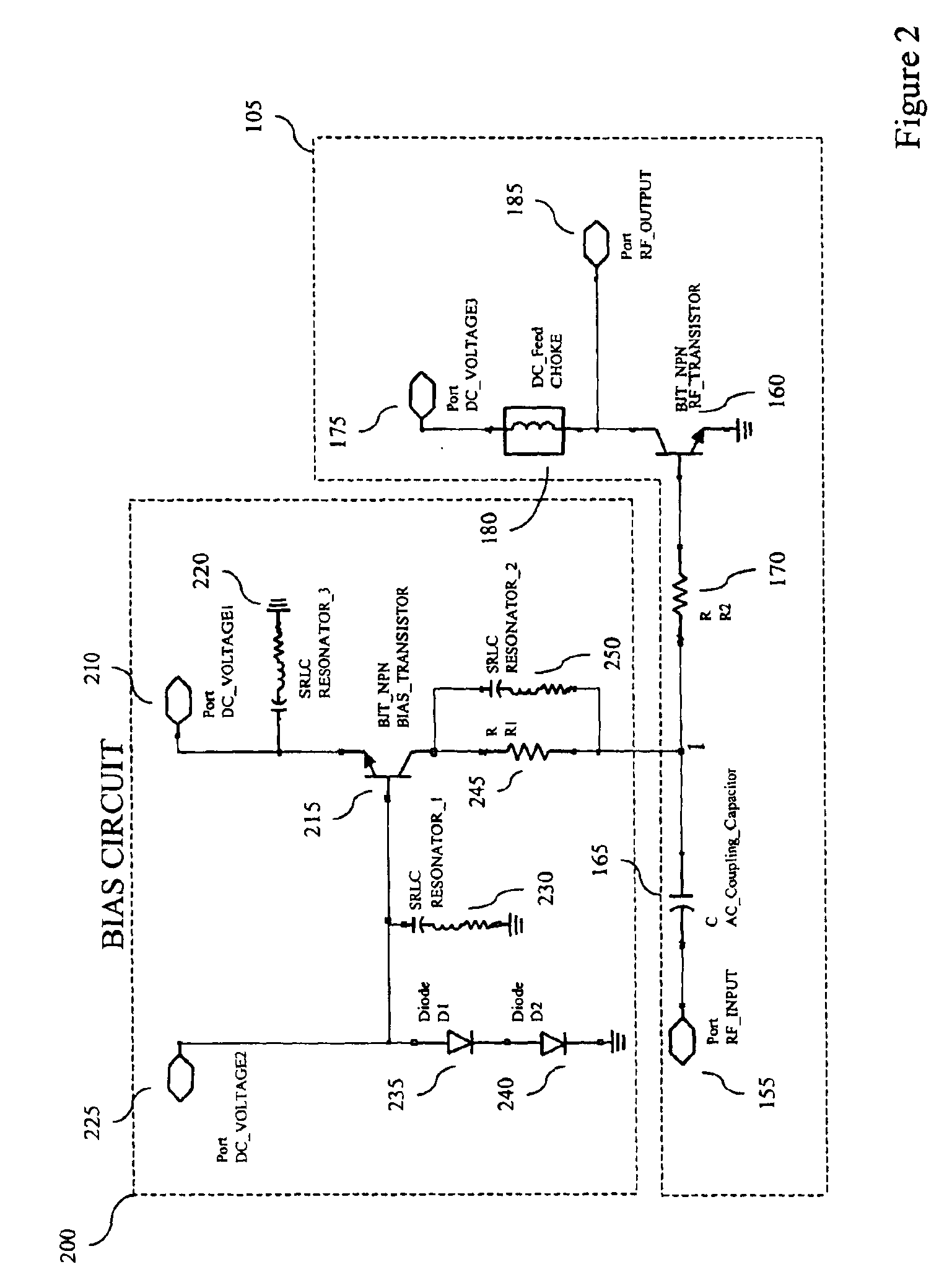
[0023]An HBT, like a bipolar junction transistor (“BJT”), requires a direct-current current (“DC”) bias signal comprising both a voltage and a current to be applied to its input terminal to establish its operating point. The operating point of a transistor may be defined as the point on the transistor's characteristic curves at which the tr...


PUM


Abstract

A transistor bias circuit is provided that is capable of biasing an amplifier transistor having a control terminal, a current-sink terminal, and a current-source terminal in order to control inter-modulation and linearize the output corresponding to radio frequency and microwave frequency ranges. Additionally, an embodiment of the present circuit is capable of dynamic power control. The transistor bias circuit according to the present invention utilizes a leakage current to alter the electrical characteristics of the amplifier transistor. The bias circuit comprises a bias transistor having a control terminal, a current-sink terminal, and a current-source terminal. Additionally, at least one DC input port, at least one resonator element, a diode element, and a resistive element is provided.

Description

RELATED APPLICATIONS[0001]The present application is related to and claims priority benefit of the filing date of a U.S. provisional patent application titled: HBT BIAS CIRCUIT LINEARIZATION AND DYNAMIC POWER CONTROL; Ser. No. 60 / 410,842, filed Sep. 13, 2002, which is hereby incorporated by reference into the present application.BACKGROUND[0002]The present invention is generally directed to the design and implementation of complex circuits to reduce distortion and linearize the output corresponding to radio frequency (RF) and microwave frequency ranges. An embodiment of the present integrated circuitry (IC) is configured to use a combination of Heterojunction Bipolar transistors (HBT) and resonant circuits to effectively provide linearization and dynamic power control for RF and microwave signals.[0003]Today, one problem with operating a power amplifier at low distortion levels is that the efficiency of the amplifier circuit is greatly reduced because it is not amplifying at its hig...

Claims


Application Information

Patent Timeline
Patent Type & Authority Patents(United States)
IPC IPC(8): H03L5/00H03F3/04H03F1/02H03F1/30H03F1/32
CPCH03F1/0261H03F1/30H03F1/32H03F1/302H03F2200/225
Inventor BARRY, DARYL W.CHUN, CARL S.HAN, SANGWOOSMITH, THOMAS B.TRIPPE, MICHAEL W.
Owner SKYWORKS SOLUTIONS INC
Why Eureka
Try Eureka