Object location system and method

a technology of object location and object location, applied in the direction of direction finders, instruments, measurement devices, etc., can solve the problems of small differences in clock frequencies, inability to determine the location of objects, and signal dispersion in cables, etc., and achieve the effect of high-quality position measurements

Inactive Publication Date: 2005-04-19
ZEBRA TECH CORP
View PDF20 Cites 183 Cited by
  • Summary
  • Abstract
  • Description
  • Claims
  • Application Information

AI Technical Summary

Benefits of technology

[0015]In view of the foregoing, it is a feature of the present invention to provide highly accurate position measurements (e.g. +/−1 foot or better) by providing a measurement apparatus, preferably utilizing UWB signals, that is disposed at each of the monitoring stations; a timing reference clock to synchronize the frequency of counters within the

Problems solved by technology

One drawback of this approach was signal dispersion in the cable.
However, a drawback of this approach relates to the fact that these systems are plesiochronous, or “nearly” synchronous; i.e., timing reference signals were arbitrarily close in frequency (within some specified limits), but were not sourced from the same clock signal.
As each monitoring station had an independent clock source, small differences in clock frequencies degraded accuracy in position measurement.
While this was suitable for frequency synchronization in benign outdoor conditions, monitoring stations operating indoors or in urban environments could not generally rely upon receiving a GPS timing signal, and consequently, object location could not be determined.
However, a drawback was the lack of a provision to reset the counters or otherwise control the relative phase between them.
Non-compensated phase offset between counters degraded position accuracy.
A serious drawback of this approach was that, upon receiving a first tag transmission, the system was temporarily “disarmed” and thus unable to process a second tag transmission until the network completed the transfer of measurement data.
Thus, it was possible that one or more tag transmissions were lost in the process.
Thus, one drawback of this approach was that each monitoring station had to be equipped with two distinct RF receivers—a first to sense the tag transmission and a second to sense the synchronization signal.
A

Method used


Image

  • Object location system and method
  • Object location system and method
  • Object location system and method

Examples


Embodiment Construction

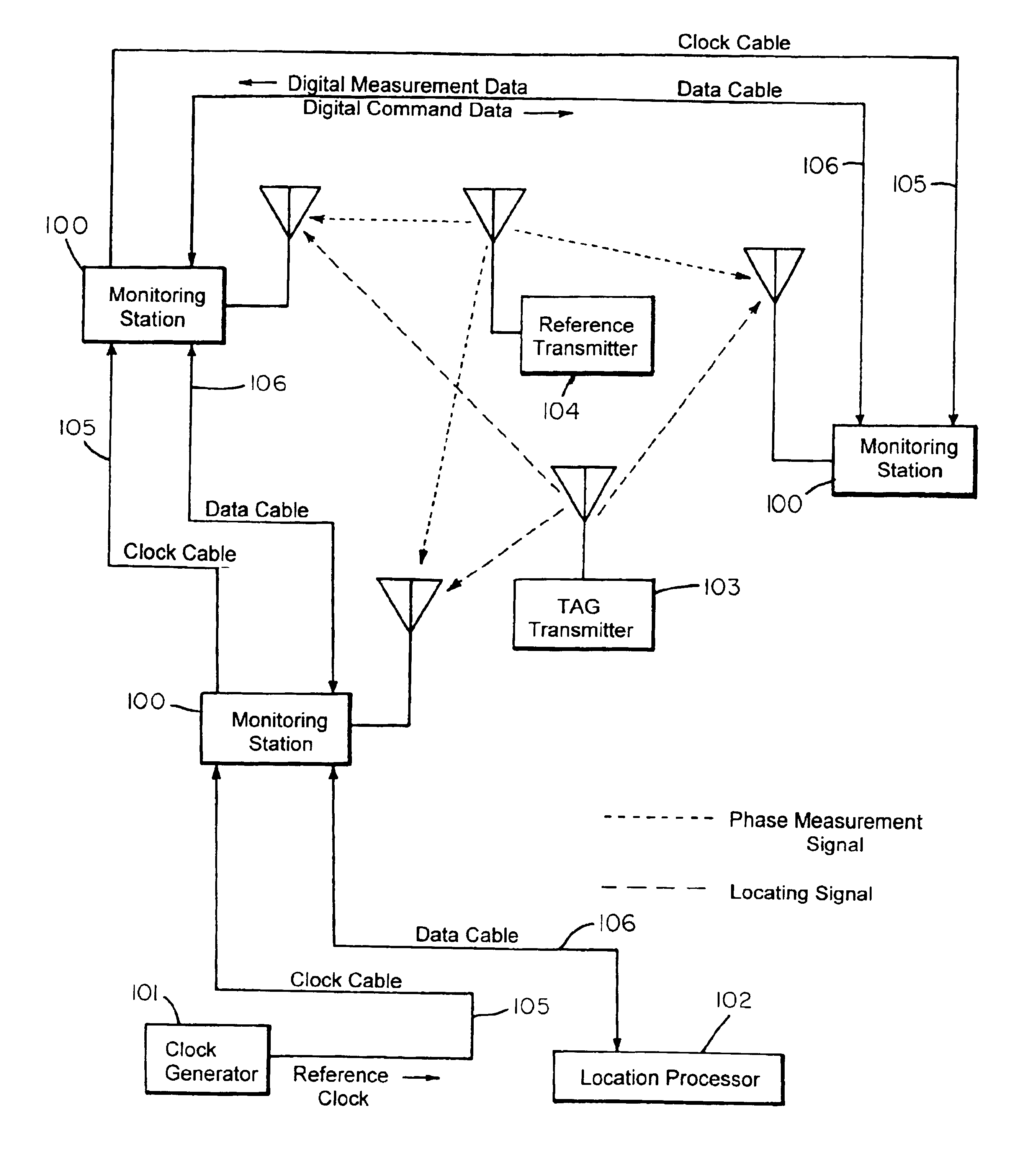
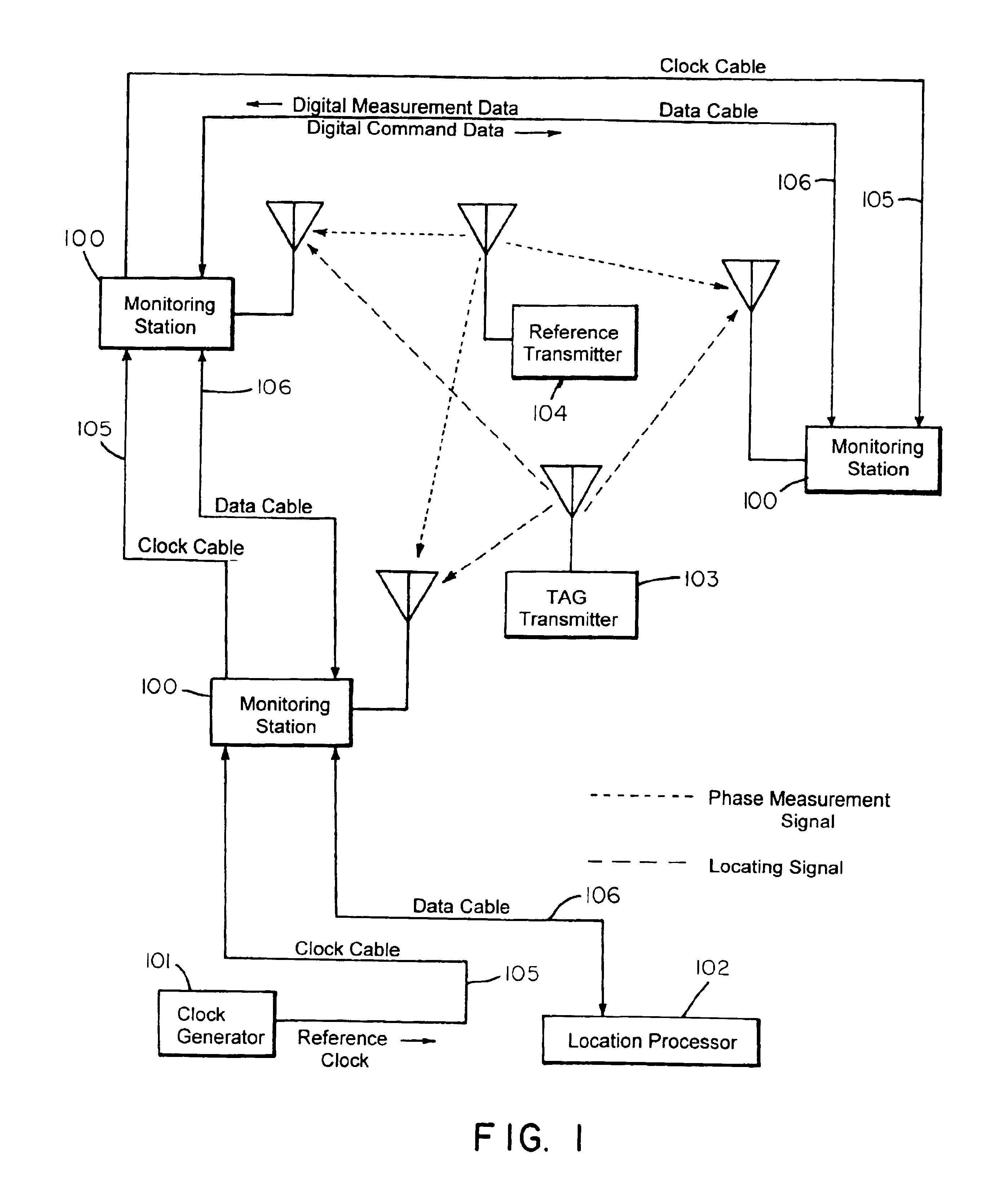
[0031]FIG. 1 shows a radio frequency locating system useful for determining the position of an object. The object to be located has an associated transmitter 103, preferably an UWB transmitter, that transmits a TOA timing pulse, and optionally, an information packet that may include, but not limited to, ID information and a sequential burst count. At least one other transmitter, depicted as reference transmitter 104, is positioned within and / or about a monitored region.

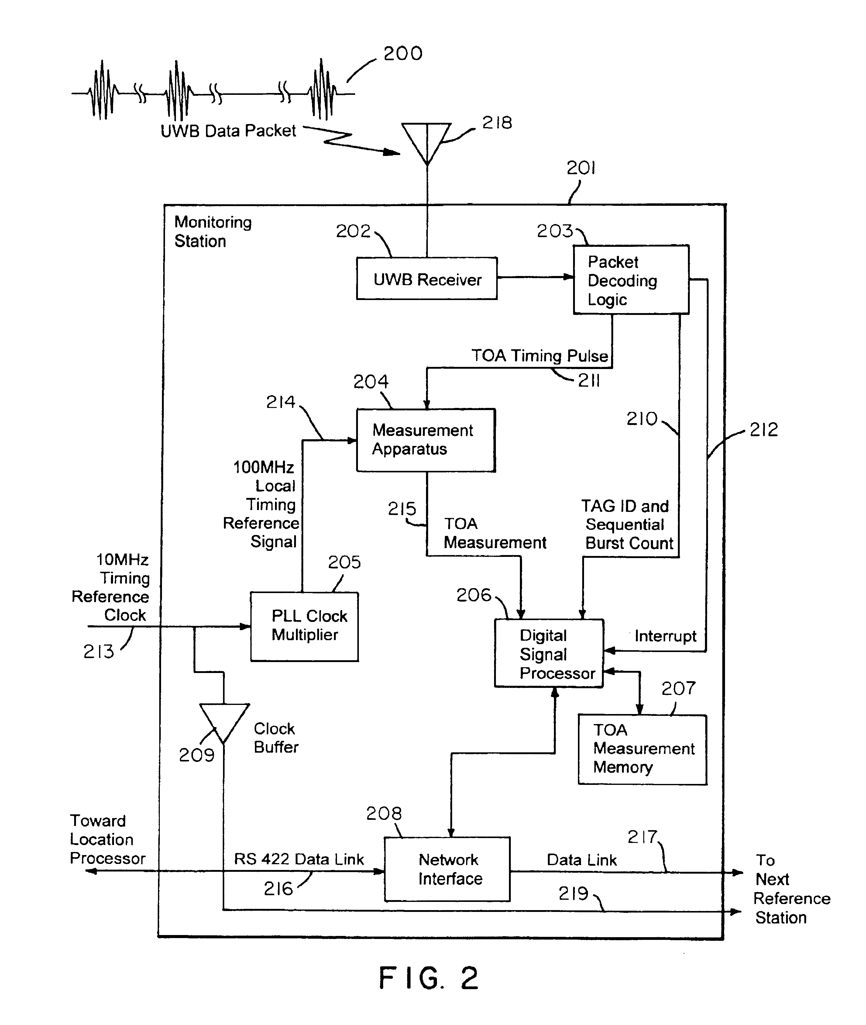
[0032]One or more (preferable three or more) monitoring stations 100 are also positioned at predetermined coordinates within and / or around the monitored region. These monitoring stations sense signals transmitted by the object tag 103 and reference transmitter 104. Each of the monitoring stations 100 includes a receiver for receiving transmissions (preferably UWB transmissions), and preferably, a packet decoding circuit that extracts a TOA timing pulse train, transmitter ID, packet number and / or other information that...


PUM


Abstract

An RF object locating system and method that uses or includes a set of N (N>2) receivers (monitoring stations) located at fixed positions in and/or about a region to be monitored, one or more reference transmitters that transmit a timing reference, a location processor that determines object location based on time-of-arrival measurements, and at least one object having an untethered tag transmitter that transmits RF pulses, which may additionally include object ID or other information. Free-running counters in the monitoring stations, whose phase offsets are determined relative to a reference transmitter, are frequency-locked with a centralized reference clock. Time-of-arrival measurements made at the monitoring stations may be stored and held in a local memory until polled by the location processor. The invention permits rapid acquisition of tag transmissions thereby enabling the monitoring of large numbers of objects, and also provides a unique approach to data correlation in severe multipath environments.

Description

BACKGROUND[0001]This invention relates to a radio frequency (“RF”) object location method and apparatus. More specifically, this invention relates to system architecture, as well as an improved synchronization method and apparatus for locating an object in a multipath, reverberation, or other noisy environment.[0002]RF location systems may be used to keep track of objects such as inventory, materiel, equipment, personnel, and other items. In such systems, objects to be located typically utilize individual transmitters or transponders, i.e., RF tags. To locate the object, various techniques have previously been used to process received signals.[0003]In one prior systems, RF sensors (also referred to as “monitoring stations”) were positioned at known coordinates within and / or about an area to be monitored. RF emissions from tags associated with the object were received and processed by these sensors. Signal processing schemes included measuring relative signal strength, angle of arriv...

Claims


Application Information

Patent Timeline
IPC IPC(8): G01S5/02G01S5/06G01S19/11
CPCG01S5/06G01S5/0226
Inventor RICHLEY, EDWARD A.FONTANA, ROBERT J.PERINO, DONALD V.AMETI, AITAN
Owner ZEBRA TECH CORP
Why Eureka
Try Eureka