Rolling radar array with a track

a radar array and track technology, applied in the direction of polarised antenna unit combinations, basic electric elements, antennas, etc., can solve the problems of mechanical fatigue, component failure, sliprings being a limitation feature of revolving antenna designs,

Inactive Publication Date: 2005-04-19
LOCKHEED MARTIN CORP
View PDF6 Cites 24 Cited by
  • Summary
  • Abstract
  • Description
  • Claims
  • Application Information

AI Technical Summary

Problems solved by technology

However, these components are subject to significant stress, resulting in mechanical fatigue and ultimately component failure.
Sliprings are a limiting feature in revolving antenna designs.
Commercially available sliprings have limited current transmission capability.
This limits the power that can be supplied to a conventional radar array.
Future radar arrays may require 1000 amps or more, and may not be adequately supported using sliprings.
Fluid cooling presents another limitation on conventional arrays.

Method used


Image

  • Rolling radar array with a track
  • Rolling radar array with a track
  • Rolling radar array with a track

Examples


Embodiment Construction

[0062]The parent application, U.S. patent application Ser. No. 10 / 119,576, filed Apr. 10, 2002 is incorporated by reference herein in its entirety.

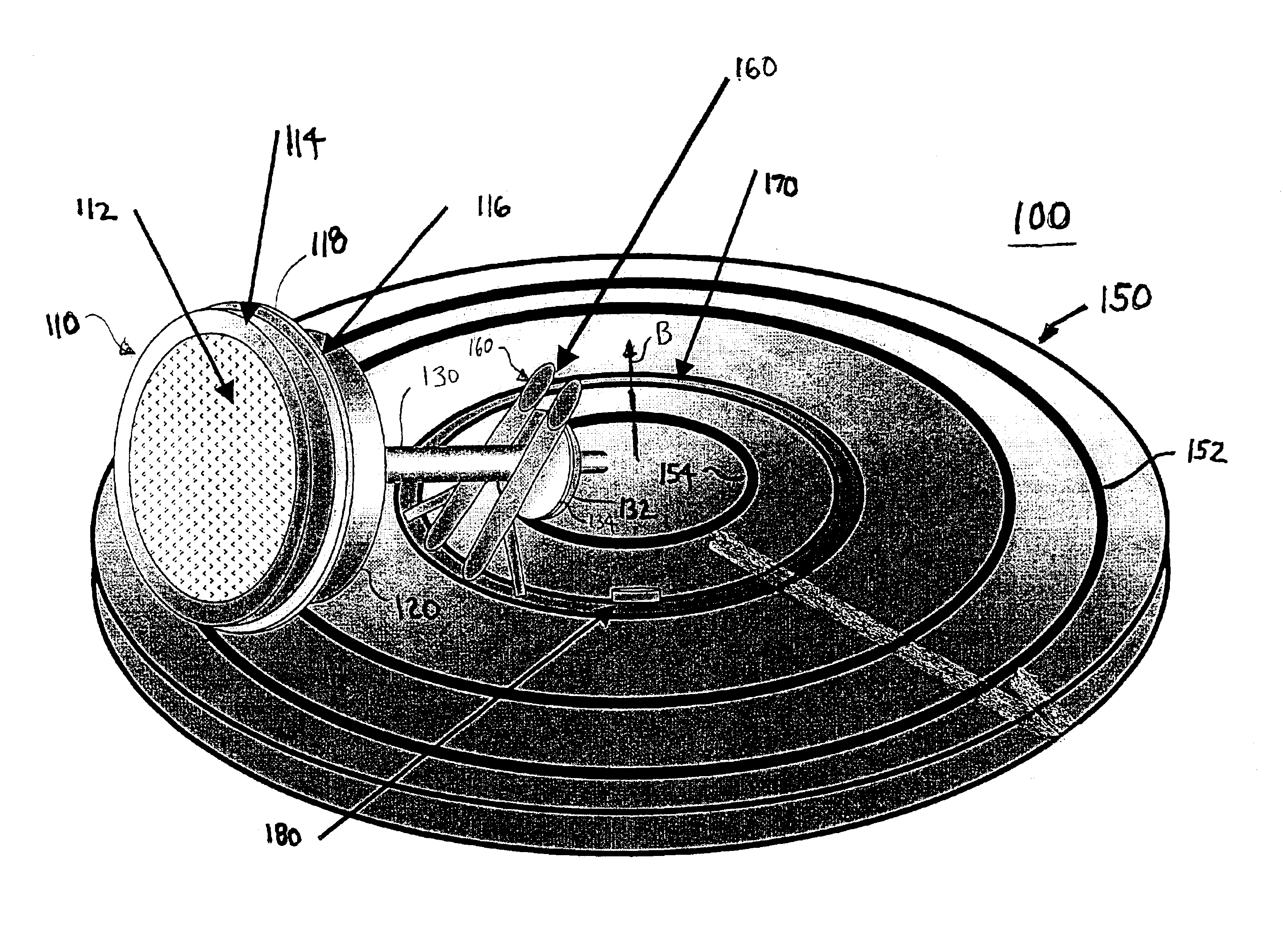
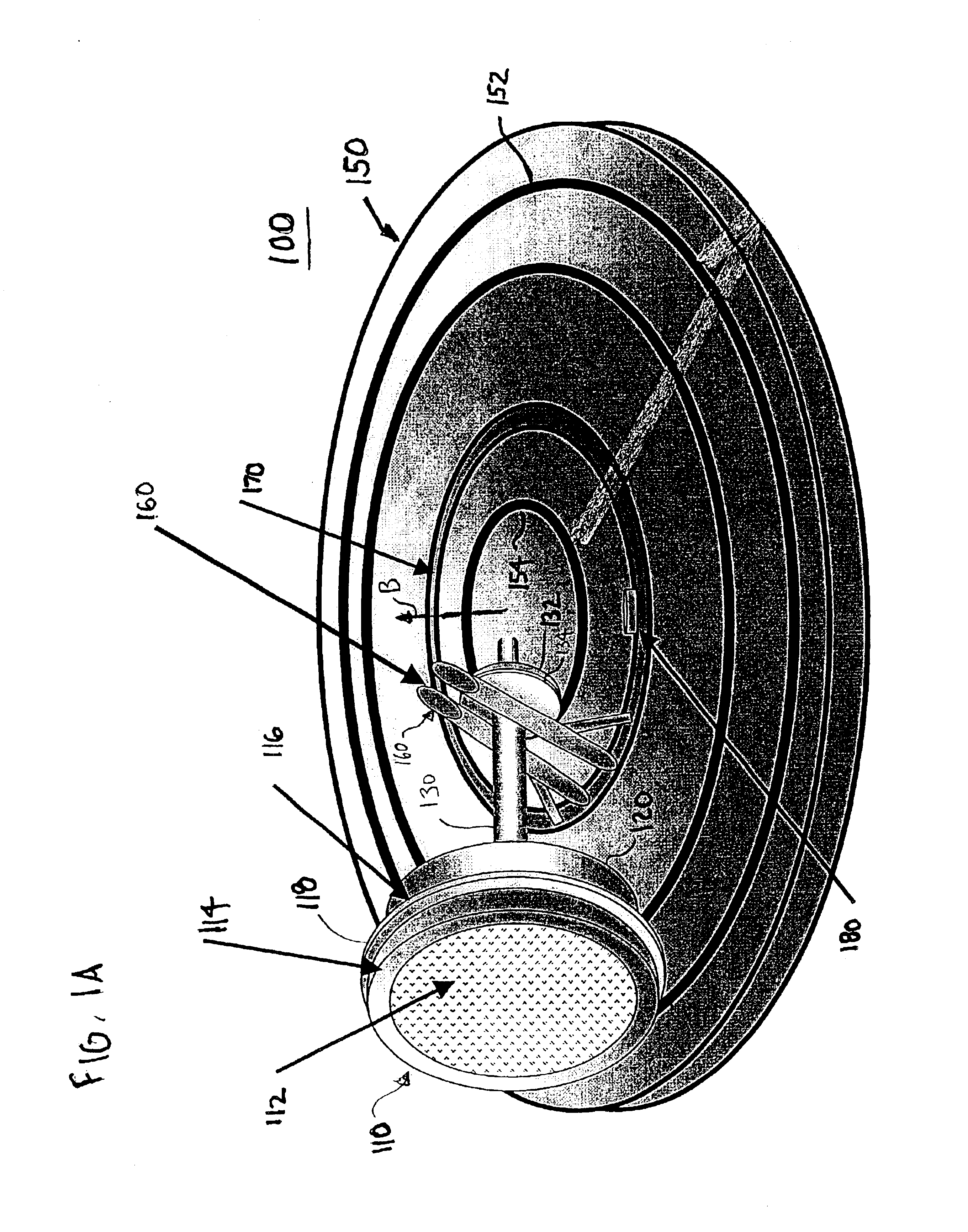
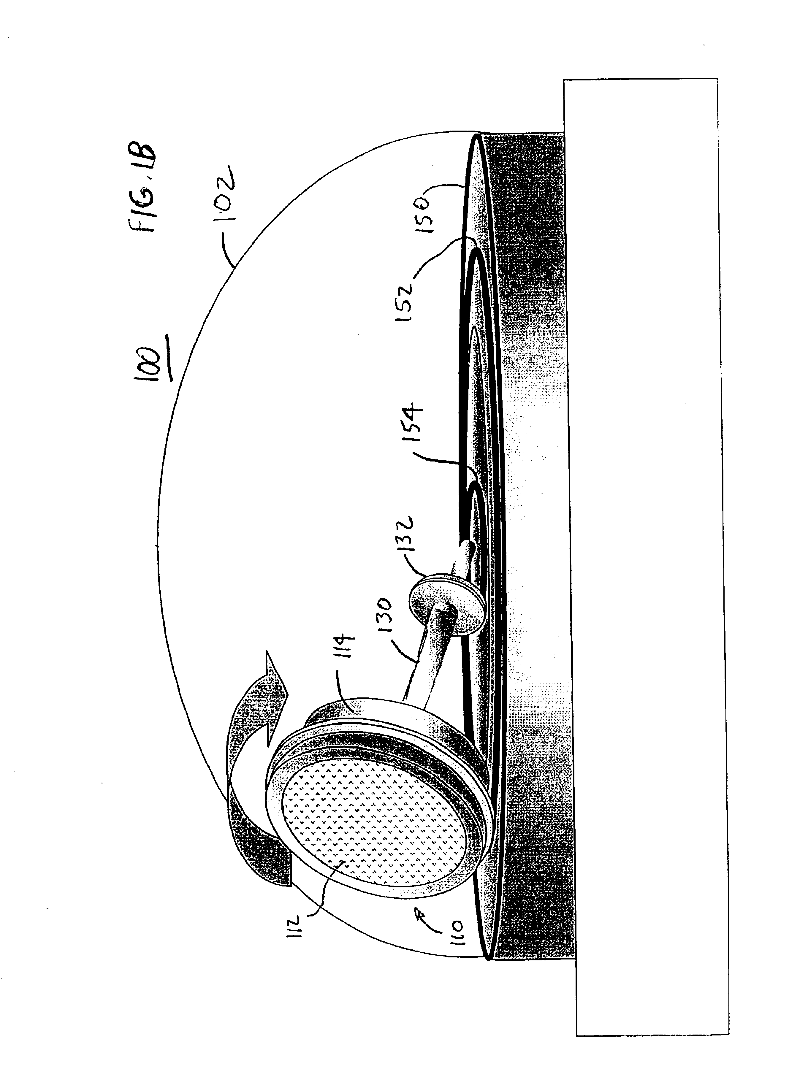
[0063]FIGS. 1A, 1B and 2 show a first exemplary embodiment of a radar system 100 according to the present invention. FIGS. 1A and 2 show the array assembly 110 and platform 150. FIG. 1B also shows a radome 102 covering the assembly 110 and platform 150. The radar system 100 comprises an array assembly 110 and a platform 150. The array assembly 110 includes a radar array 112 mounted on a first circular wheel 114 having a first size S1. In addition to the array 112, the first wheel 114 may contain transmitters, receivers, processing and cooling mechanisms. The first wheel 114 has a circumferential portion adapted to engage a path 152 disposed on a platform 150 for revolving the radar array 112 about the platform. An axle 130 is coupled to the first wheel 114. The wheel 114 rotates about the axle 130 as the radar array 112 revolves around th...


PUM


Abstract

A radar antenna system comprises a wheel, cone or frustum having an axis. The wheel, cone or frustum has a circumferential portion adapted to engage at least one path disposed on a platform for revolving the radar array about the platform. A radar array is mounted on the wheel, cone or frustum, with the axis normal to a face of the radar array. The wheel, cone or frustum rotates about the platform as the radar array revolves around the platform during operation.

Description

[0001]This application is a continuation in part of U.S. patent application Ser. No. 10 / 119,576, filed Apr. 10, 2002.FIELD OF THE INVENTION[0002]The present invention relates to radar array systems, and more particularly to radar arrays mounted on rotating array platforms.BACKGROUND OF THE INVENTION[0003]Arrays such as RF beam scanning arrays and the like are often implemented using large rotating array platforms that revolve the array in the azimuth direction. For example, the platform may rotate so as to slew the array by a predetermined azimuth angle, or to scan the entire range of azimuth angles available to the antenna at a constant angular rate. Traditional approaches to implementing rotating radar array platforms involve the use of a variety of mechanical or electromechanical parts including sliprings for providing array power, and large load-bearing bearings to support the rotating platform. However, these components are subject to significant stress, resulting in mechanical...

Claims


Application Information

Patent Timeline
Patent Type & Authority Patents(United States)
IPC IPC(8): H01Q3/08H01Q9/04H01Q9/36H01Q21/24
CPCH01Q3/08H01Q21/24H01Q9/36H01Q9/0464
Inventor TIETJEN, BYRON W.
Owner LOCKHEED MARTIN CORP
Why Eureka
Try Eureka