Microscope having a contrast-increasing image a acquisition apparatus

a technology of contrast-increasing image and acquisition apparatus, which is applied in the field of microscopes, can solve the problems of time-consuming processes, impaired image quality, and inability to accurately detect the image, so as to reduce the overall recording time, the overall acquisition time is also correspondingly reduced, and the spacing is sufficient

Inactive Publication Date: 2005-04-19
LEICA MICROSYSTEMS CMS GMBH
View PDF5 Cites 3 Cited by
  • Summary
  • Abstract
  • Description
  • Claims
  • Application Information

AI Technical Summary

Benefits of technology

[0009]The arrangement according to the present invention thus combines the advantages of a planar image sensor which makes possible rapid imaging of the desired image area, and a high-resolution point-by-point scan. The use of the same image sensors in the same beam path for both operating modes yields an economical arrangement.
[0012]A further advantageous embodiment of the invention consists in the fact that the stop possesses several stop openings. Said stop openings are preferably of point-like configuration and possess a sufficient spacing from one another that no overlap of flare occurs between the images of the individual stop openings. As a result, several image points of the sensor are exposed simultaneously in one step. The overall acquisition time of an image is also correspondingly reduced. For example, in the case of ten stop openings which thus simultaneously expose ten image points simultaneously, the overall recording time can be decreased by a factor of ten.
[0013]In a further advantageous embodiment of the invention, the stop opening is configured in such a way that it approximately corresponds, in one or two axes, to the size of one image point of the image sensor. In the case of a slit-shaped stop, for example, the width of the stop corresponds to one image point of the image sensor. In the case of a point-like stop, the length and width of the stop opening correspond to the length and width, respectively, of one image point of the sensor. It is thereby possible effectively to prevent flare from being sensed by the image sensor, since only exactly one image point of the image sensor is illuminated. Optimum light efficiency is only achieved, however, with very precise alignment of the stop opening and image sensor. To allow at least slight tolerances in this context, it is advantageous if the stop opening is dimensioned slightly larger than one image point on the image sensor.
[0014]A further advantageous embodiment of the invention consists in the fact that an additional evaluation unit is present. The purpose of this evaluation unit is to analyze and process the image data of the image sensor. It thus ascertains the correct position of the individual image points from the image of the stop on the image sensor, and transmits to the memory unit the respective image values of the center image point on the image sensor. As a result, it is not necessary to transmit the present position of the specimen to the memory unit, since that can be obtained from the data of the two-dimensional image sensor. This also makes possible scanning with a highly tolerance-affected positioning unit. It is also possible to use, instead of a positioning unit that activates individual positions in each case, a drive which implements a continuous motion of the specimen.

Problems solved by technology

The disadvantage of these cameras, however, is that the image quality is impaired by aberrations in the optics and by flare.
The disadvantage of such an apparatus is that image scanning takes a relatively long time, so that alignment of the image area and correct focusing also represent time-consuming processes.

Method used


Image

  • Microscope having a contrast-increasing image a acquisition apparatus
  • Microscope having a contrast-increasing image a acquisition apparatus
  • Microscope having a contrast-increasing image a acquisition apparatus

Examples


Embodiment Construction

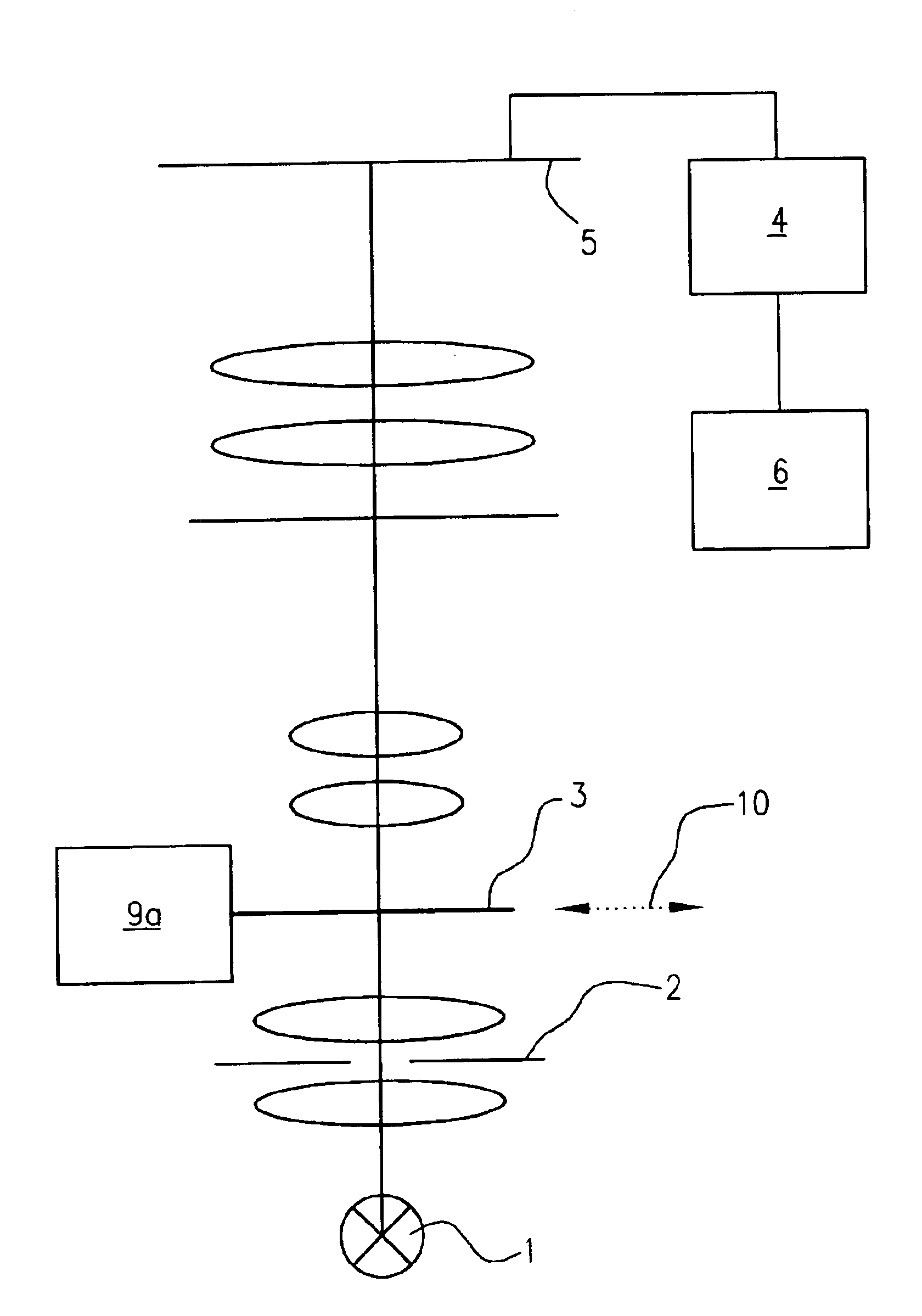
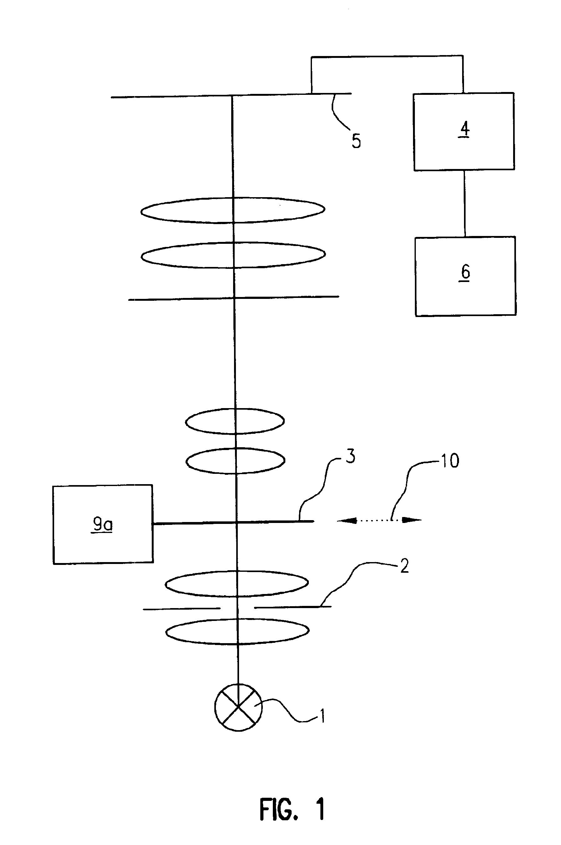
[0021]FIG. 1 schematically depicts an arrangement according to the present invention in general and highly simplified form. The light of a light source 1 is incident via a stop 2 on specimen 3, and is imaged via further lens systems onto image sensor 5. The latter is connected to a memory unit 4, and that in turn to an evaluation unit 6. Specimen 3 can be moved in the plane of arrow (10). It should be appreciated that although arrow (10) only depicts one axis of movement, positioning unit (9a) is capable of scanning an area. i.e., scanning in two axes. Since the lens systems arranged between specimen 3 and image sensor 5 are known per se, they have been inserted into FIGS. 1 and 2 without reference characters and without more detailed explanation.

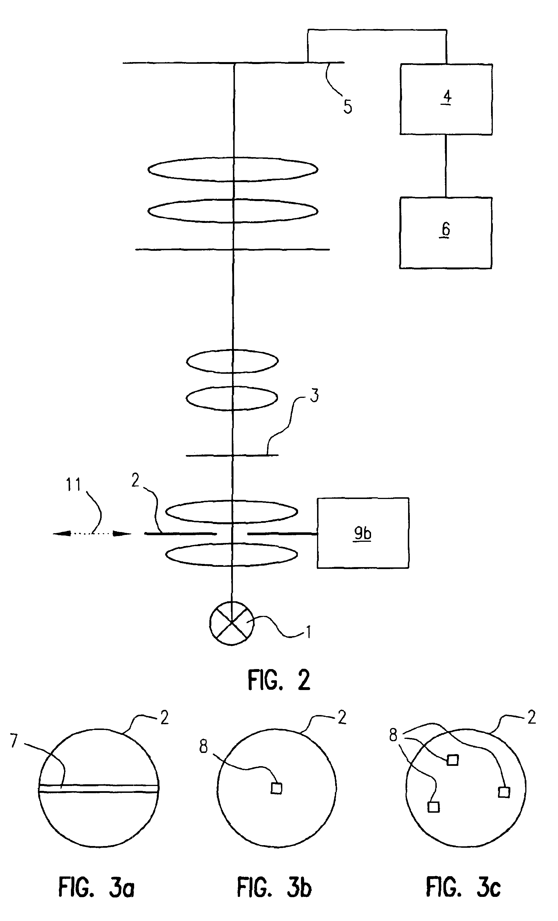
[0022]FIG. 2 shows an arrangement similar to that in FIG. 1, only stop 2 being moved in this case. This is again illustrated by arrow (11). As previously mentioned, it should be appreciated that although arrow (11) only depicts one axis of ...


PUM


Abstract

The invention concerns a microscope having an image sensor (5) for recording the microscope images. The specimen (3) to be examined can be scanned by means of a stop (2) in the beam path of the illumination unit and a positioning unit which moves the specimen (3) or the stop (2). Opening the stop (2) or removing it from the beam path permits the entire image to be scanned with the image sensor (5).

Description

CROSS REFERENCE TO RELATED APPLICATIONS[0001]This application claims priority of the German patent application 101 48 188.8 which is incorporated by reference herein.FIELD OF THE INVENTION[0002]The invention concerns a microscope that is equipped with an image sensor for recording and storing the microscope images. A plurality of different image recording apparatuses for microscopes are known. Usually a video camera is connected to the observation beam path. Video cameras of this kind at present usually have two-dimensional image sensors, so that the entire image is recorded in one operation.BACKGROUND OF THE INVENTION[0003]These video cameras are easy to operate and quickly furnish a good-quality image. The disadvantage of these cameras, however, is that the image quality is impaired by aberrations in the optics and by flare. Scanning microscopes, for example, are used to eliminate these disadvantages. One such microscope is described in EP-A-0 810 457. The disadvantage of such an ...

Claims


Application Information

Patent Timeline
Patent Type & Authority Patents(United States)
IPC IPC(8): G02B21/00G02B21/36G02B21/06H04N5/225
CPCG02B21/361G02B21/002
Inventor BLOEDORN, JOCHENRUEHL, HELMUT
Owner LEICA MICROSYSTEMS CMS GMBH
Why Eureka
Try Eureka