Head suspension having reduced heat deformation

a suspension and heat deformation technology, applied in the direction of magnetic recording, data recording, instruments, etc., can solve the problem of deformation in the suspension b

Inactive Publication Date: 2005-04-19
TOSHIBA STORAGE DEVICE CORP
View PDF9 Cites 34 Cited by
  • Summary
  • Abstract
  • Description
  • Claims
  • Application Information

AI Technical Summary

Benefits of technology

[0012]In this structure, because the write wiring of the circuit pattern, for example, is arranged substantially symmetrical with respect to the center line of the suspension body, heat deformation of part of the suspension body, especially when a write current flows through the write wiring, is eliminated.

Problems solved by technology

However, if a localized thermal load is placed on the suspension body 1B when the disk device is operating, deformation occurs in the suspension 1 having the MR head.
This phenomenon decreases if, after application of the write current, there is a wait time of several seconds until the entire head (suspension and coil) becomes warm before writing begins, but this several seconds wait time is a hindrance in a disk device mass production line.

Method used


Image

  • Head suspension having reduced heat deformation
  • Head suspension having reduced heat deformation
  • Head suspension having reduced heat deformation

Examples


first embodiment

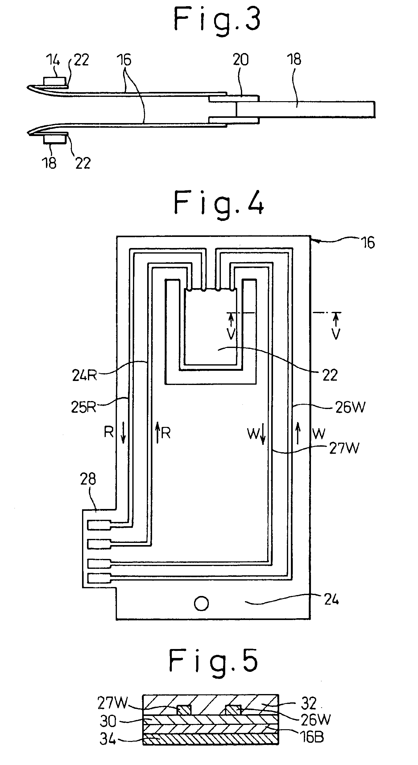
[0033]FIG. 4 is a top view of the suspension of the present invention. FIG. 5 is a sectional view of a portion of the suspension along the line V—V of FIG. 4. In FIGS. 4 and 5, the suspension 16 has an attachment portion 24 for attachment to the spacer 20 which is attached to the actuator 18, and a tongue 22 for attaching the slider 14. A circuit pattern including a read wiring 24R and 25R and a write wiring 26W and 27W is formed on one surface of the suspension 16. The read wiring 24R and 25R is formed along one side of the suspension 16 in order to supply a read current R to the MR head formed in the slider 14 (not shown), and the write wiring 26W and27W is formed along the other side of the suspension 16 to supply a write current W. Also, the suspension 16 has a connection region 28 at which the suspension is connected to a flexible print board.

[0034]As shown in FIG. 5, the suspension 16 is of a laminated structure comprising a suspension body 16B formed from stainless steel, a p...

second embodiment

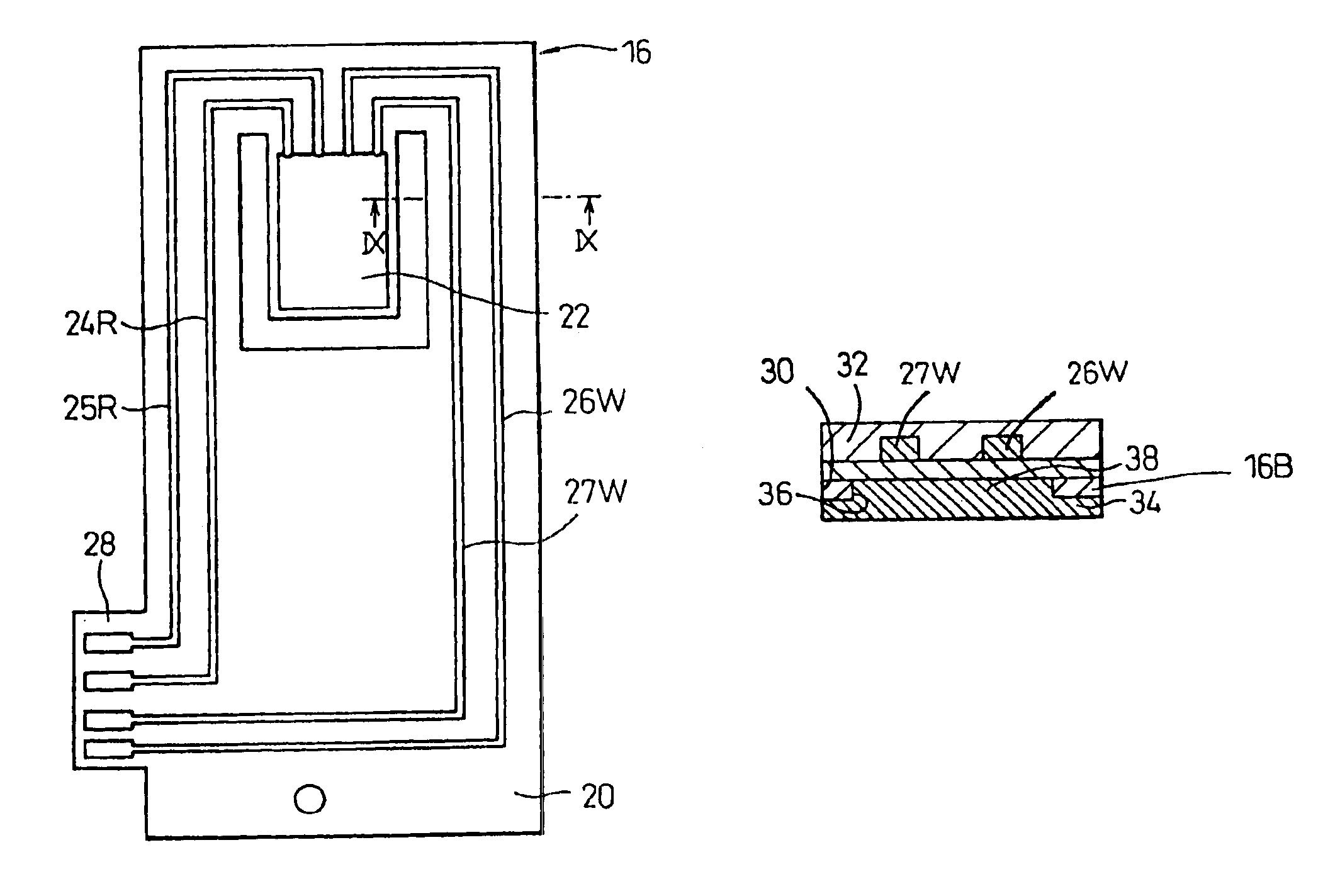
[0039]FIG. 8 is a top view of the suspension according to the present invention. FIG. 9 is a sectional view of a portion of the suspension along the line IX—IX of FIG. 8. FIG. 10 is a bottom view of a portion of the suspension of FIGS. 8 and 9, without the metal layer. In FIGS. 8 and 9, the suspension 16 has an attachment portion 24 for attachment to a spacer 20, a tongue 22, and a connection region 28 at which the suspension is connected to a flexible print board. Circuit pattern including a read wiring 24R and 25R and a write wiring 26W and 27W is formed on one surface of the suspension 16.

[0040]The suspension 16 is a laminated structure comprising a suspension body 16B formed from stainless steel, a PI protective coating 30 applied to one surface of the suspension body 16B, a copper circuit pattern including read wiring 24R and 25R and write wiring 26W and 27W formed on the protective coating 30, and a PI protective coating 32 covering the read wiring 24R and 25R and the write wi...

third embodiment

[0042]FIG. 11 is a top view of the suspension according to the present invention. FIG. 12 is a sectional view of a portion of the suspension along the line XI—XI of FIG. 11. In FIGS. 11 and 12, the suspension 16 has an attachment portion 24 for attachment to a spacer 20, a tongue 22, and a connection region 28 at which the suspension is connected to a flexible printed board. A circuit pattern, including read wiring 24R and 25R and write wiring 26W and 27W, is formed on one surface of the suspension 16. The suspension 16 is of a laminated structure comprising a suspension body 16B formed of stainless steel, a PI protective coating 30 applied to one surface of the suspension body 16B, a copper circuit pattern including read wiring 24R and 25R and write wiring 26W and 27W formed on the protective coating 30, and a PI protective coating 32 covering the read wiring 24R and 25R and the write wiring 26W and 27W.

[0043]In this embodiment, each of the read wiring 24R and 25R and the write wir...


PUM

PropertyMeasurementUnit
thicknessaaaaaaaaaa
thicknessaaaaaaaaaa
thicknessaaaaaaaaaa

Abstract

A suspension is made of a suspension body of a stainless plate, a resin protective layer on one surface of the suspension body, a circuit pattern including read wiring and write wiring on the protective layer, and a metal layer provided on the other surface of the suspension body. In this arrangement, heat deformation of the suspension is alleviated when a write current is applied.

Description

BACKGROUND OF THE INVENTION[0001]1. Field of the Invention[0002]The present invention relates to a suspension structure for a disk device.[0003]2. Description of the Related Art[0004]A hard disk device such as a magnetic disk device or the like is provided with a plurality of disks for storing information, and heads, such as MR heads or the like, for writing information to the disks and reading information from the disks. Each head is provided on a slider, and each slider is floatably disposed with respect to the disk by means of a suspension structure. Each suspension is coupled to an actuator.[0005]A head is connected to a control circuit by lead wires which extend along the suspension. Recently, a circuit pattern has been formed on the suspension, instead of lead wires, and the circuit pattern is connected via a flexible print board to the print board of the control circuit. In this way, by forming the circuit pattern on the suspension, the disk device can be miniaturized and a h...

Claims


Application Information

Patent Timeline
Patent Type & Authority Patents(United States)
IPC IPC(8): G11B5/48G11B21/21
CPCG11B5/4833
Inventor YAMAOKA, NOBUYOSHIAOKI, KENICHIRO
Owner TOSHIBA STORAGE DEVICE CORP
Why Eureka
Try Eureka