Method and apparatus for using data compression as a means of increasing buffer bandwidth

a data compression and buffer bandwidth technology, applied in the field of computer memory controllers, can solve the problems of increasing the amount of memory required to store data and increasing the size of data blocks, and achieve the effects of increasing the overall bandwidth of the memory controller, and increasing the effective bandwidth of associated memory

Inactive Publication Date: 2005-04-19
MAXTOR
View PDF11 Cites 187 Cited by
  • Summary
  • Abstract
  • Description
  • Claims
  • Application Information

AI Technical Summary

Benefits of technology

[0012]In accordance with another embodiment of the present invention, a memory controller for use in connection with a computer storage device that is capable of increasing the effective bandwidth of associated memory is provided. The memory controller provides at least one interface for receiving or sending data. The memory controller further provides a data compression engine for compressing data received at the interface. Associated with or integral to the memory controller is memory, such as an SDRAM buffer or cache. Data received from a data producer or source is compressed by the data compression engine and is stored in the memory by a memory manager. When data stored in the memory is required at an interface of the memory controller, it is read from the memory by the memory manager, and expanded to its original form by a data decompression engine. The uncompressed data is then available to the interface interconnected to the data consumer. Because compression of the data received from a data producer at the interface results in fewer bytes of information that must be written to and read from the memory, the effective bandwidth of the memory is increased. Furthermore, because the data compression and decompression engine or engines are capable of compressing and decompressing data faster than it can be stored in the memory, the overall bandwidth of the memory controller is increased as compared to a conventional memory controller.

Problems solved by technology

If the compression operation resulted in an increase in the size of the data block, which would increase the amount of memory required to store the data (i.e., the data is pathological), the data is written to memory in uncompressed form.

Method used


Image

  • Method and apparatus for using data compression as a means of increasing buffer bandwidth
  • Method and apparatus for using data compression as a means of increasing buffer bandwidth
  • Method and apparatus for using data compression as a means of increasing buffer bandwidth

Examples


Embodiment Construction

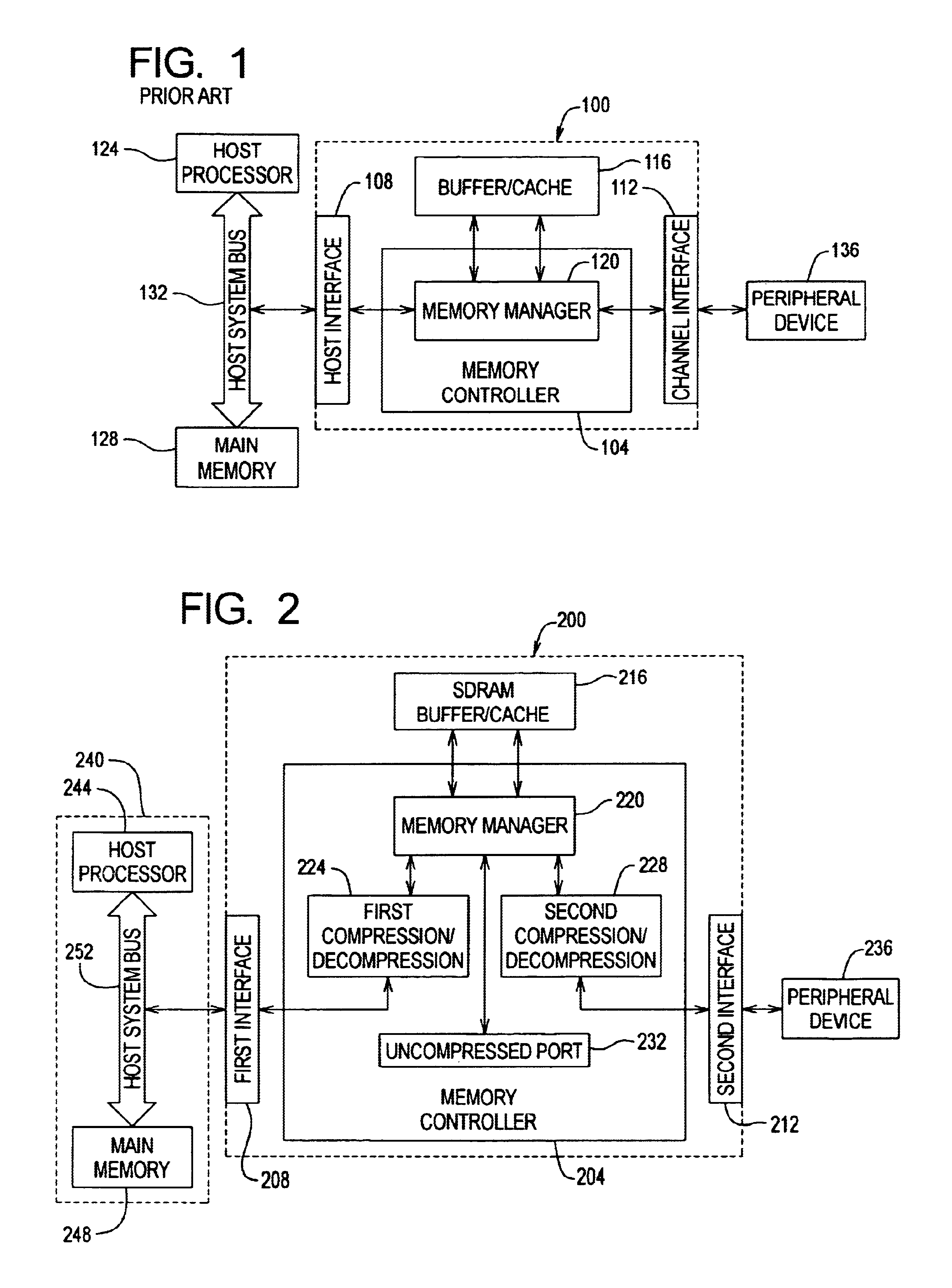
[0016]With reference now to FIG. 1, a memory controller system 100 in accordance with the prior art is illustrated. The conventional memory controller system 100 generally includes a memory controller 104, a first or host interface 108, a second or channel interface 112, and memory 116. In addition, the memory controller 104 may include a memory manager 120. In a typical implementation of a conventional memory controller system 100, the first interface is interconnected to a host processor 124 and to main memory 128 through a system bus 132, and the second interface 112 is interconnected to a peripheral device 136.

[0017]In operation, the conventional memory controller system 100 receives data at one of the first or second interfaces 108 or 112 for transfer to the other of the first or second interfaces 108 or 112. If the consumer of the data or the interface 108 or 112 through which the consumer of data is interconnected to the conventional memory controller 104 is not ready to rece...


PUM


Abstract

A method and apparatus for increasing the bandwidth of a memory controller system are provided. According to the invention, data received at an interface of a memory controller system is compressed in the memory controller by a compression engine for storage in associated memory. The address of the data written to memory is maintained in a memory controller. When data is read from the memory for provision to an interface of the memory controller, the memory manager retrieves the data from memory and provides it to a decompression engine. The decompression engine restores the data to its original, uncompressed form. The data is then provided to the appropriate interface.

Description

CROSS REFERENCE TO RELATED APPLICATIONS[0001]Priority is claimed from U.S. Provisional Patent Application Ser. No. 60 / 229,924 filed Sep. 1, 2000, entitled “USING DATA COMPRESSION AS A MEANS OF INCREASING EFFECTIVE BUFFER BANDWIDTH” the disclosure of which is incorporated herein by reference in its entirety.FIELD OF THE INVENTION[0002]The present invention relates to computer memory controllers. In particular, the present invention relates to increasing the effective bandwidth of disk drive controllers using data compression.BACKGROUND OF THE INVENTION[0003]Memory controllers are a common feature in connection with computing devices. Among the functions of memory controllers are interface timing, refresh generation, arbitration and access to a memory component. Memory controllers may also allocate and control access to memory provided for the purpose of buffering data or as a data cache in connection with exchanges of data between a first interface or channel and a second interface o...

Claims


Application Information

Patent Timeline
Patent Type & Authority Patents(United States)
IPC IPC(8): G06F12/08G06F3/06
CPCG06F3/0613G06F3/0656G06F12/0868G06F3/0674G06F2212/401
Inventor PRIBORSKY, ANTHONY L.
Owner MAXTOR
Why Eureka
Try Eureka