Wire-wound leadscrew assembly with a preloaded leadscrew wire nut, and its fabrication

a wire nut and wire nut technology, which is applied in the direction of gearing, mechanical equipment, hoisting equipment, etc., can solve the problems of excessive wear of the threads limited to relatively large-size devices and coarse thread pitches, and relatively high production costs of the conventional leadscrew assembly, so as to increase the rigidity of the wire nut assembly, and maintain the flexibility of the lead screw

Inactive Publication Date: 2005-04-26
RAYTHEON CANADA LTD
View PDF13 Cites 6 Cited by
  • Summary
  • Abstract
  • Description
  • Claims
  • Application Information

AI Technical Summary

Benefits of technology

[0015]The present approach provides a wire-wound leadscrew with a preloaded leadscrew wire nut assembly. The preloading of the leadscrew wire nut assembly locally increases the rigidity of the wire-wound leadscrew within the leadscrew wire nut assembly, while maintaining the flexibility of the leadscrew outside of the leadscrew wire nut assembly, particularly in the case of the shaftless leadscrew. The engagement between the leadscrew and the leadscrew wire nut assembly is a line engagement that extends around the circumference of the leadscrew at least once, and preferably for several turns. The increased rigidity of the leadscrew / leadscrew wire nut assembly and the long line engagement permits the wire-wound leadscrew to transmit substantial force into the follower, so that the leadscrew assembly is suitable for medium-duty applications rather than being restricted to light-duty applications. Yet the wire-wound leadscrew is still sufficiently flexible that it does not require the highly precise alignment required of conventional machined leadscrews. The line contact between the thread wire and the first-nut wire and the second-nut wire avoids any digging of the leadscrew wire nut assembly into the thread wire.

Problems solved by technology

This conventional leadscrew assembly is relatively expensive to produce due to the precision machining required.
It is also limited to relatively large-size devices and coarse thread pitches because of the size of the balls used in the recirculating ball nut structure.
The conventional leadscrew assembly may be subject to excessive wear of the threads, particularly if there is any misalignment.
The approach of the '549 patent is operable for many applications but is not optimal for other applications such as those requiring medium-duty operation where there is a concern with possible misalignment.

Method used


Image

  • Wire-wound leadscrew assembly with a preloaded leadscrew wire nut, and its fabrication
  • Wire-wound leadscrew assembly with a preloaded leadscrew wire nut, and its fabrication
  • Wire-wound leadscrew assembly with a preloaded leadscrew wire nut, and its fabrication

Examples


Embodiment Construction

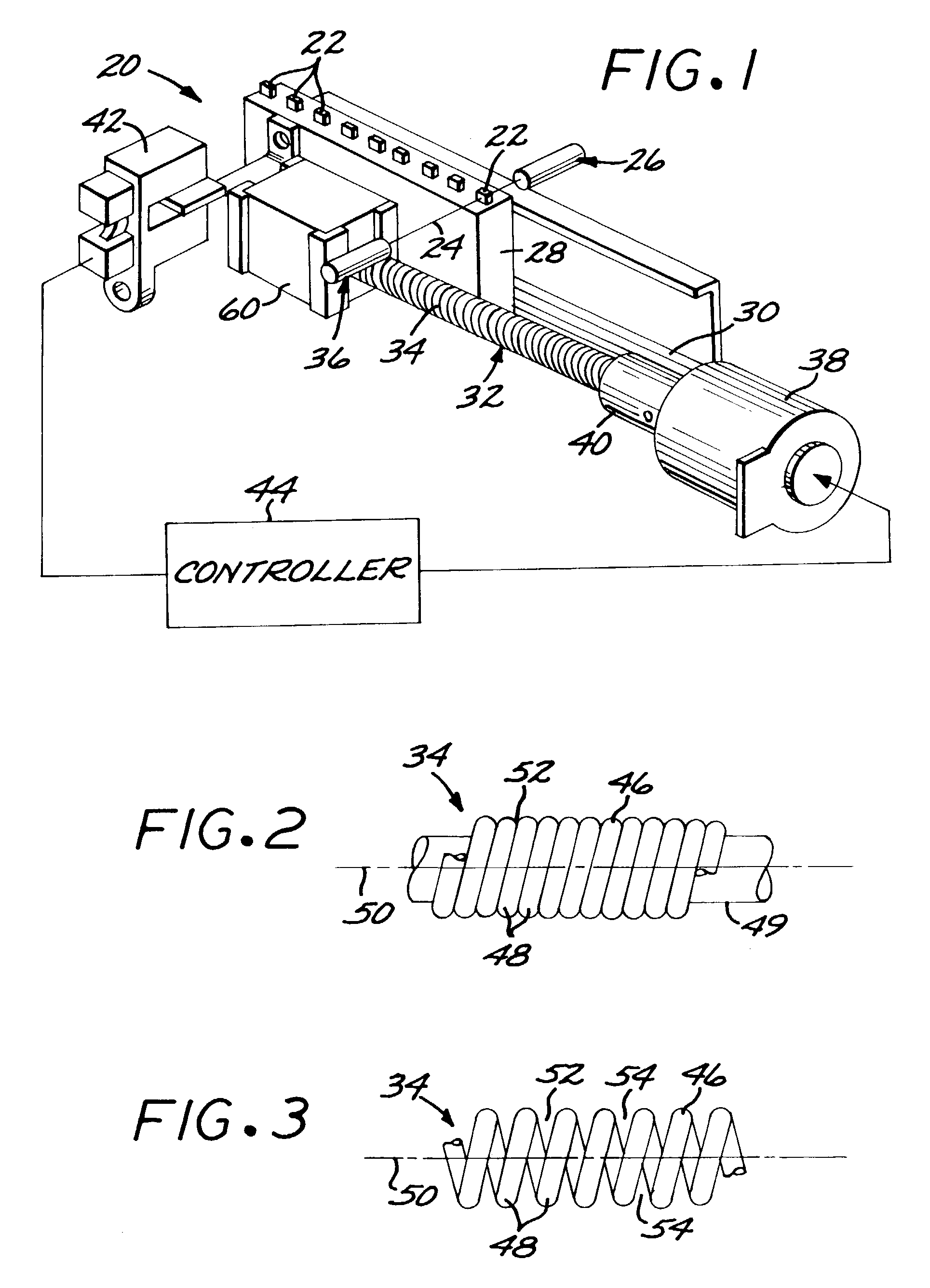
[0024]FIG. 1 depicts a leadscrew assembly 20 in one of its applications. As illustrated, the leadscrew assembly 20 includes a filter module which controllably places a light filter 22 into a light path 24 of an optical fiber light transmission system 26 and thereafter controllably removes the light filter 22 from the light path 24. The leadscrew assembly 20 is presented as an example of a leadscrew drive and its application, but the invention is not so limited. The leadscrew assembly 20 comprises a linearly movable support 28 upon which at least one light filter 22, and preferably a plurality of light filters 22, are mounted. The movable support 28 in the illustrated embodiment is a linear slide mechanism that is linearly movable upon a linear bearing 30. A drive mechanism 32 is operably connected to the movable support 28 to controllably move the light filters 22 into and out of the light path 24.

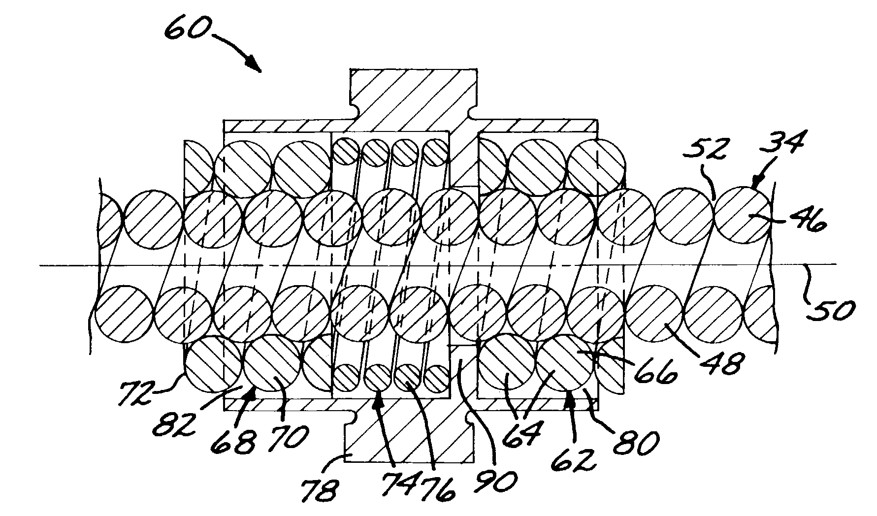
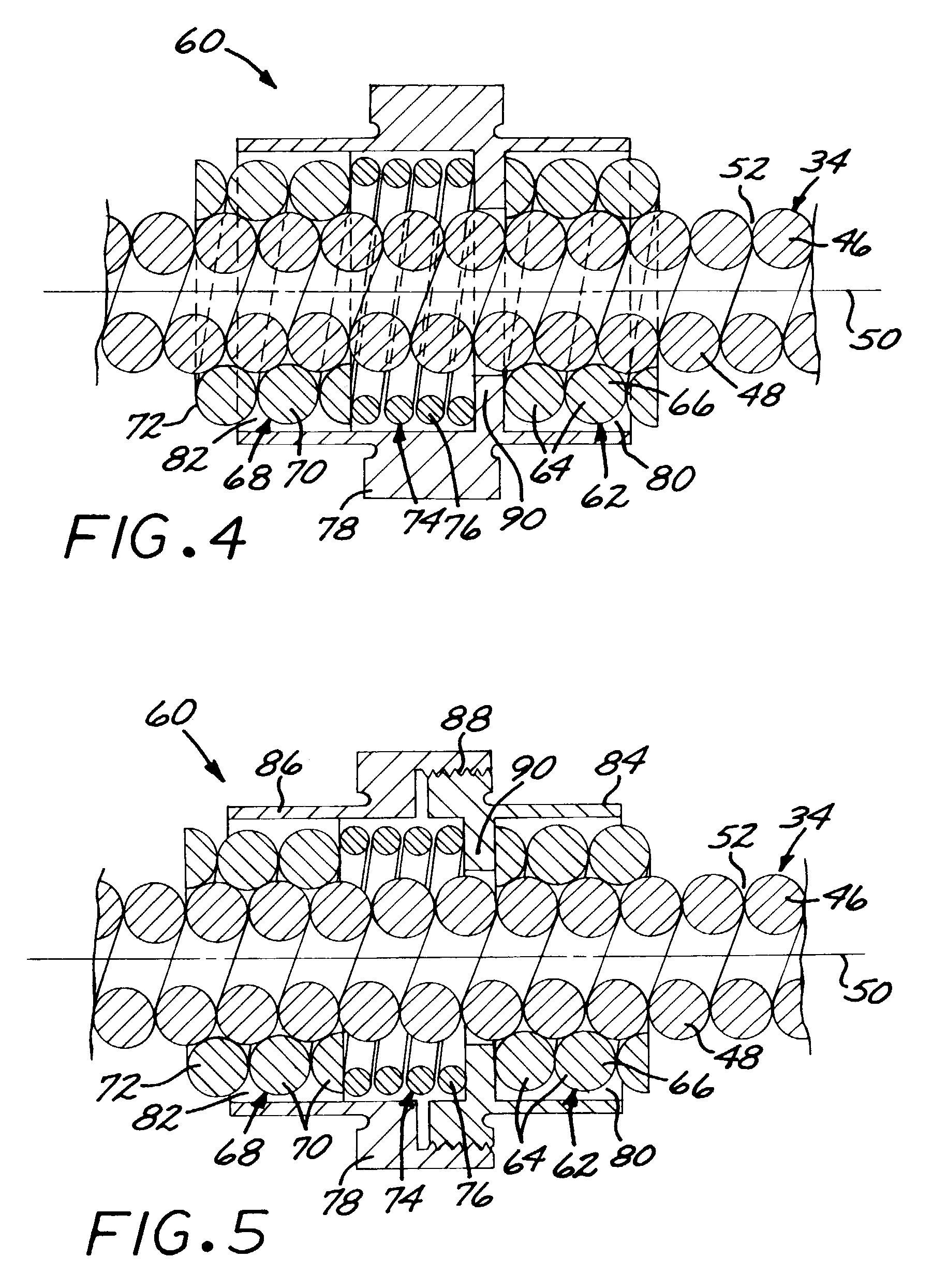
[0025]The drive mechanism 32 includes a leadscrew 34 drivably connected to the movable...


PUM


Abstract

A leadscrew assembly has a wire-wound leadscrew driven by a mechanical drive. A preloaded leadscrew wire nut assembly serving as a leadscrew follower includes a first wire nut having at least one turn of a first-nut wire overlying and engaged to the groove between the turns of the thread wire, and a second wire nut having at least one turn of a second-nut wire overlying and engaged to the groove between the turns of the thread wire. The second wire nut is spaced apart from the first wire nut along a leadscrew axis. The leadscrew wire nut assembly further includes a compressed preload spring maintaining a compression preload against the second wire nut, and a wire-nut-assembly housing overlying the first wire nut, the second wire nut, and the preload spring. The wire-nut-assembly housing maintains the preload spring in compression.

Description

[0001]This application is a continuation-in-part of application Ser. No. 10 / 084,704, filed Feb. 26, 2002, for which priority is claimed and whose disclosure is incorporated by reference; and is a continuation-in-part of application Ser. No. 10 / 265,814, filed Oct. 7, 2002, for which priority is claimed and whose disclosure is incorporated by reference[0002]This invention relates to a mechanical movement to translate rotational to linear motion and, more particularly, to a wire-wound leadscrew linear-movement assembly.BACKGROUND OF THE INVENTION[0003]Electric motors commonly produce a rotational output, but many mechanisms require that a linear movement be driven by the motor. A leadscrew assembly is one approach for translating the rotational movement of the motor to the required linear movement. In the conventional leadscrew assembly, the thread of an externally threaded leadscrew engages a recirculating ball nut structure, which in turn is engaged to the structure to be driven line...

Claims


Application Information

Patent Timeline
Patent Type & Authority Patents(United States)
IPC IPC(8): F16H25/24
CPCF16H25/2427Y10T74/1973Y10T74/18728Y10T74/19716
Inventor DEVENYI, GABOR
Owner RAYTHEON CANADA LTD
Why Eureka
Try Eureka