Plunging towed array antenna

Inactive Publication Date: 2005-04-26
THE UNITED STATES OF AMERICA AS REPRESENTED BY THE SECRETARY OF THE NAVY
View PDF6 Cites 27 Cited by
  • Summary
  • Abstract
  • Description
  • Claims
  • Application Information

AI Technical Summary

Benefits of technology

[0010]Accordingly, it is a general purpose and primary object of the present invention to provide a system that allows a submersible vehicl

Problems solved by technology

Mast deployed or mounted antennas are associated with several problems.
Consequently, ship speeds are limited when a mast antenna pierces the surface and a wake is created.
Known buoyant towed antenna systems, however, use a winch that cannot operate in a “freewheel” manner, i.e. the winch does not permit the spool to spin freely.
Buoyant towed antennas do not create large wakes associated with mast ant

Method used


Image

  • Plunging towed array antenna
  • Plunging towed array antenna
  • Plunging towed array antenna

Examples


Embodiment Construction

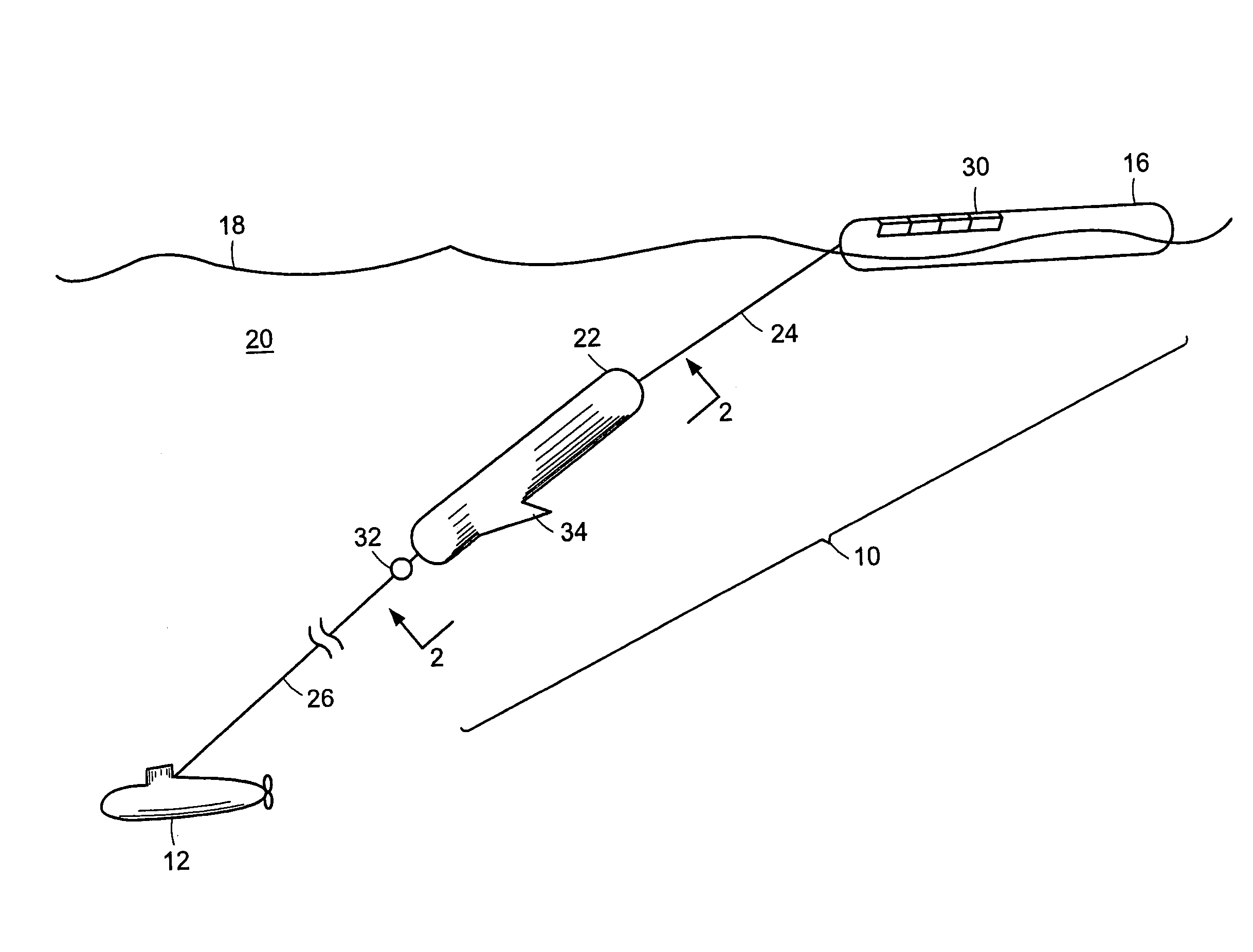
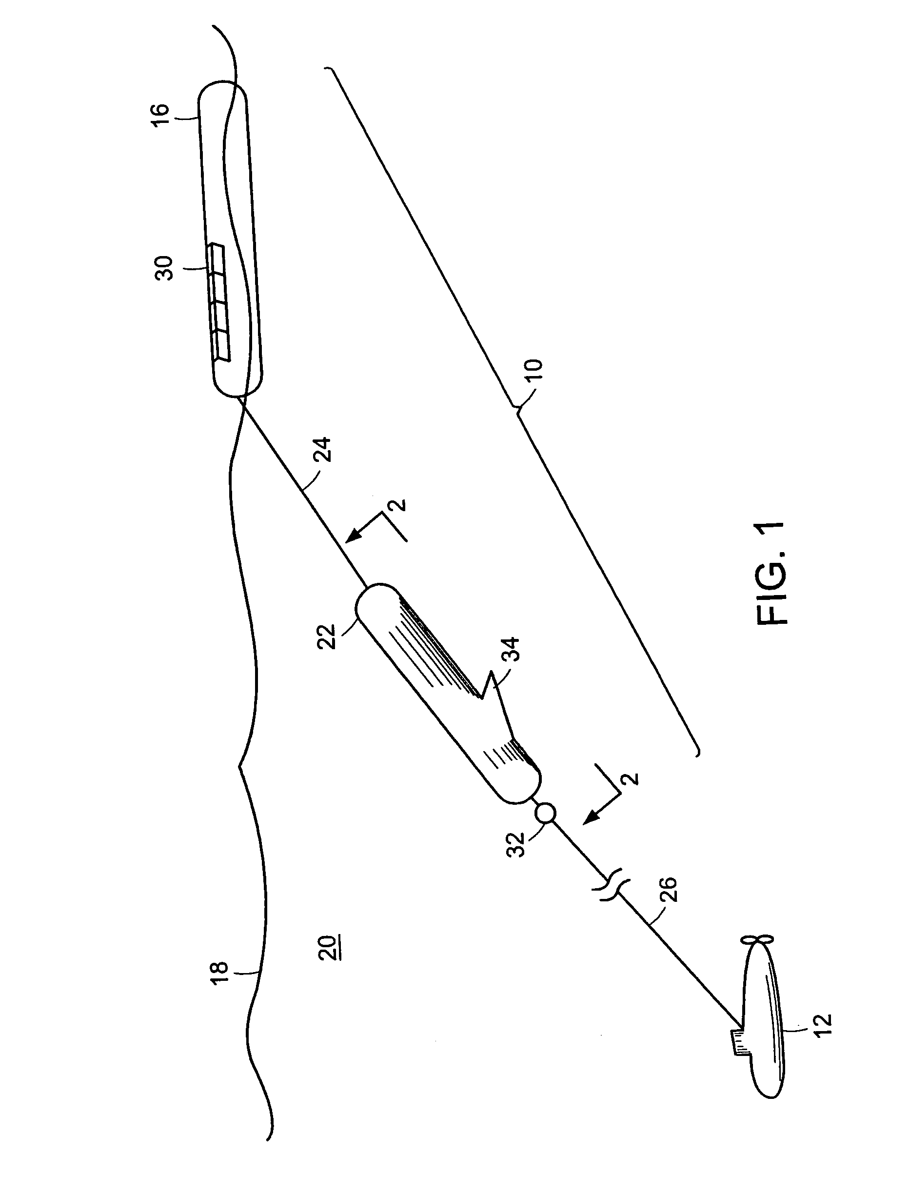
[0021]Referring now to the drawings wherein like numerals refer to like elements throughout the several views, one sees that FIG. 1 depicts the towed antenna system 10 of the present invention. The towed antenna system 10, as shown, allows a submarine or submerged platform 12 operating at relatively high-speeds to tow a buoyant body 16 on the surface 18 of a body of water 20 while eliminating intermittent plunging and wave wash-over as well as the creation of significant surface waves.

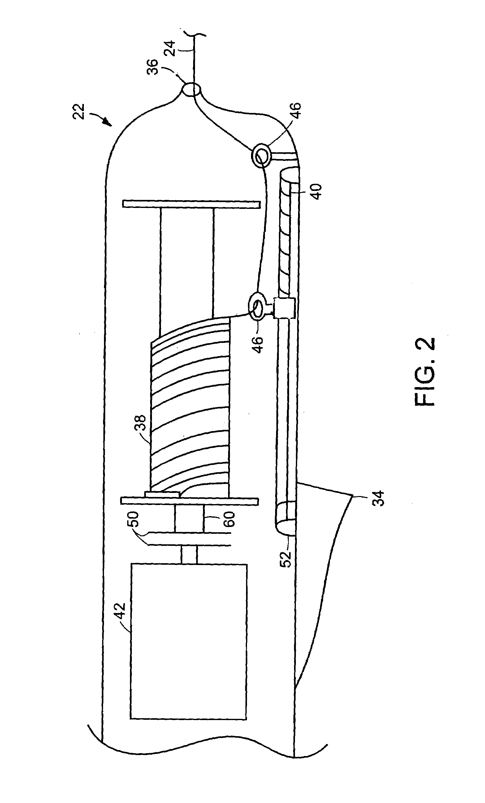
[0022]The towed antenna system 10 includes the buoyant body 16 attached to a reel housing 22 using a tether 24. The reel housing 22 is attached to the submerged platform 12 using a tow cable 26.

[0023]The buoyant body 16 floats on the surface 18 and is preferably designed to minimize turbulence and drag from any surface waves; including any design known to those skilled in the art.

[0024]The buoyant body 16 includes any known communication device 30 such as, but not limited to, an electromagnetic transmi...


PUM


Abstract

A towed antenna system and method of use includes a communication device disposed on a buoyant body attached to a housing by a tether. The housing includes a spool, a reel-wire guide, and a motor. The buoyant body and the reel housing are deployed from and towed at from a submerged platform. Hydrodynamic forces from towing prevent the buoyant body from rising to the surface while maintaining the housing at an equilibrium depth. To establish communication, the tether is released from the spool and the buoyant body rises to the surface. The tether is released until the communication session is over or until the tether is fully deployed. The reel-wire guide prevents the tether from becoming snagged during release. Once the communication session has been completed, the tether is retracted and the buoyant body re-establishes its equilibrium depth.

Description

STATEMENT OF GOVERNMENT INTEREST[0001]The invention described herein may be manufactured and used by or for the Government of the United States of America for governmental purposes without the payment of any royalties thereon or therefore.BACKGROUND OF THE INVENTION[0002](1) Field of the Invention[0003]The present invention relates to a towed antenna system and more particularly, to a plunging towed antenna system.[0004](2) Description of the Prior Art[0005]Submersible vehicles must occasionally communicate with surface ships, satellites, aircraft, and other platforms as part of their operation. In order to broadcast and receive radio transmissions, they must deploy a large antenna above the ocean surface. To maintain stealth, for example, the submarine must remain submerged during this deployment. There are several known ways to accomplish this.[0006]According to one method of antenna deployment, an antenna is mounted to a mast that is incorporated into the submarine sail. When th...

Claims


Application Information

Patent Timeline
IPC IPC(8): B63B21/56B63B21/66H02G1/10
CPCH02G1/10B63B21/66
Inventor GIESEKE, THOMAS J.
Owner THE UNITED STATES OF AMERICA AS REPRESENTED BY THE SECRETARY OF THE NAVY
Why Eureka
Try Eureka