
Walk-behind landscape edger/trencher

a technology of walking behind and landscape edger, which is applied in the direction of agricultural machines, adjusting devices, gearing, etc., can solve the problems of operator fatigue, operator constant skewing of the implement, and the handling of the side mounted trenching apparatus. achieve the effect of reducing the load of side dra

Active Publication Date: 2005-04-26
TURF TEQ
View PDF23 Cites 14 Cited by
  • Summary
  • Abstract
  • Description
  • Claims
  • Application Information

AI Technical Summary

Benefits of technology

[0006]It is an object of this invention to overcome the disadvantages of the prior art by providing a walk-behind edger / trencher having a side mounted trenching tool that minimizes the side draft loads encountered with the operation of the ground engaging and shaping tool.
[0007]It is a feature of this invention that the side mounted trenching tool can be operated into the direction of travel for the implement to provide a more efficient dispersion of the unearthed soil.
[0008]It is an advantage of this invention that the operator of the walk behind trenching apparatus will not be burdened physically by the operation of the trenching apparatus.

Problems solved by technology

Pulling a conventional “walk behind trencher” can be an arduous task and is quite tiring to the operator.
The handling of a side mounted trenching apparatus can be particularly burdensome as the rotation of the trenching tool is normally rotating in the opposite direction to the desired direction of travel of the implement, causing the operator to constantly skew the implement to the side to compensate for the operational load imposed by the trenching tool.
Using the “pull behind” version of a side mounted trencher alleviates this problem somewhat, but performance and safety problems compromise the effectiveness and tend to exhaust the operator unduly.

Method used


Image

  • Walk-behind landscape edger/trencher
  • Walk-behind landscape edger/trencher
  • Walk-behind landscape edger/trencher

Examples


Embodiment Construction

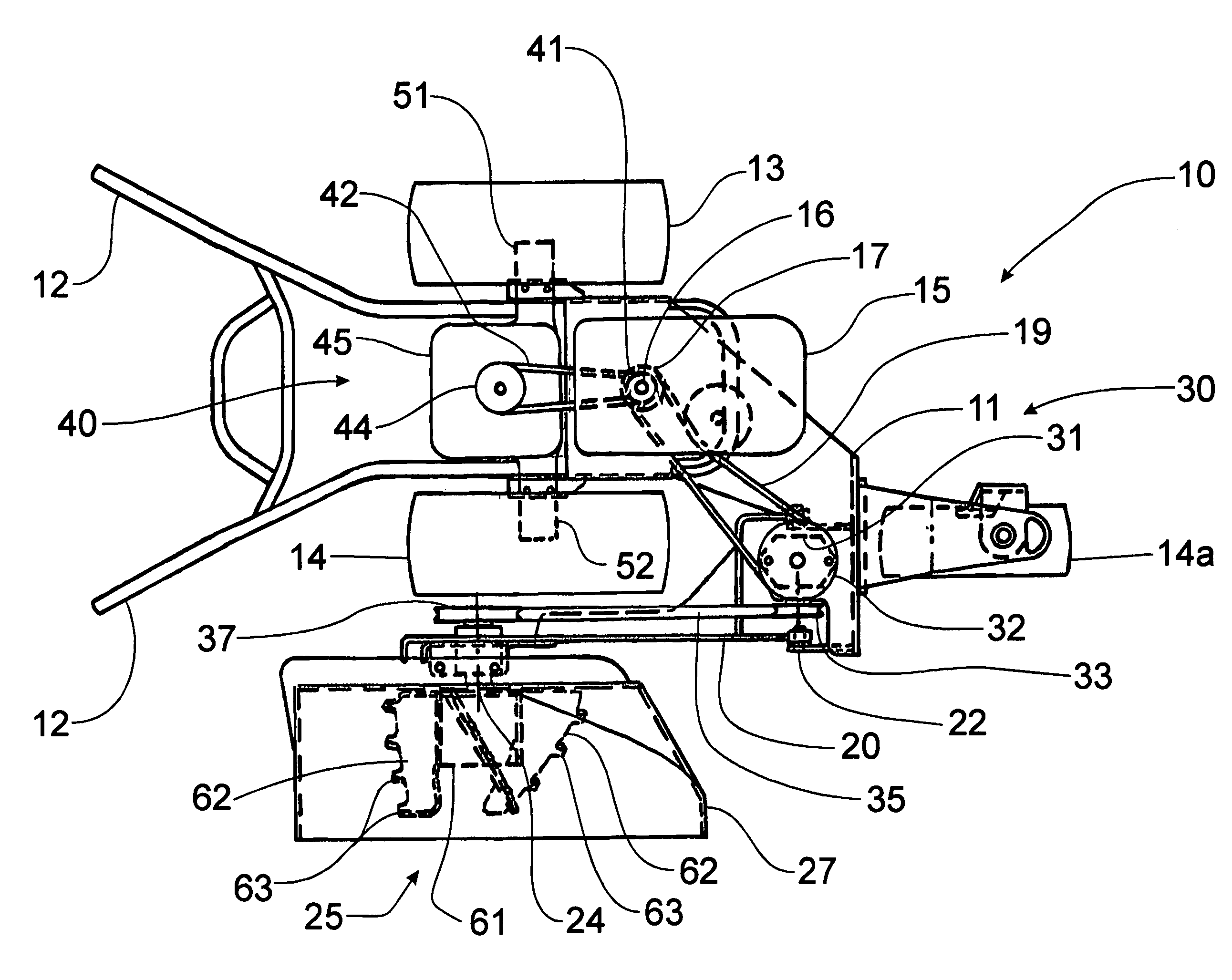
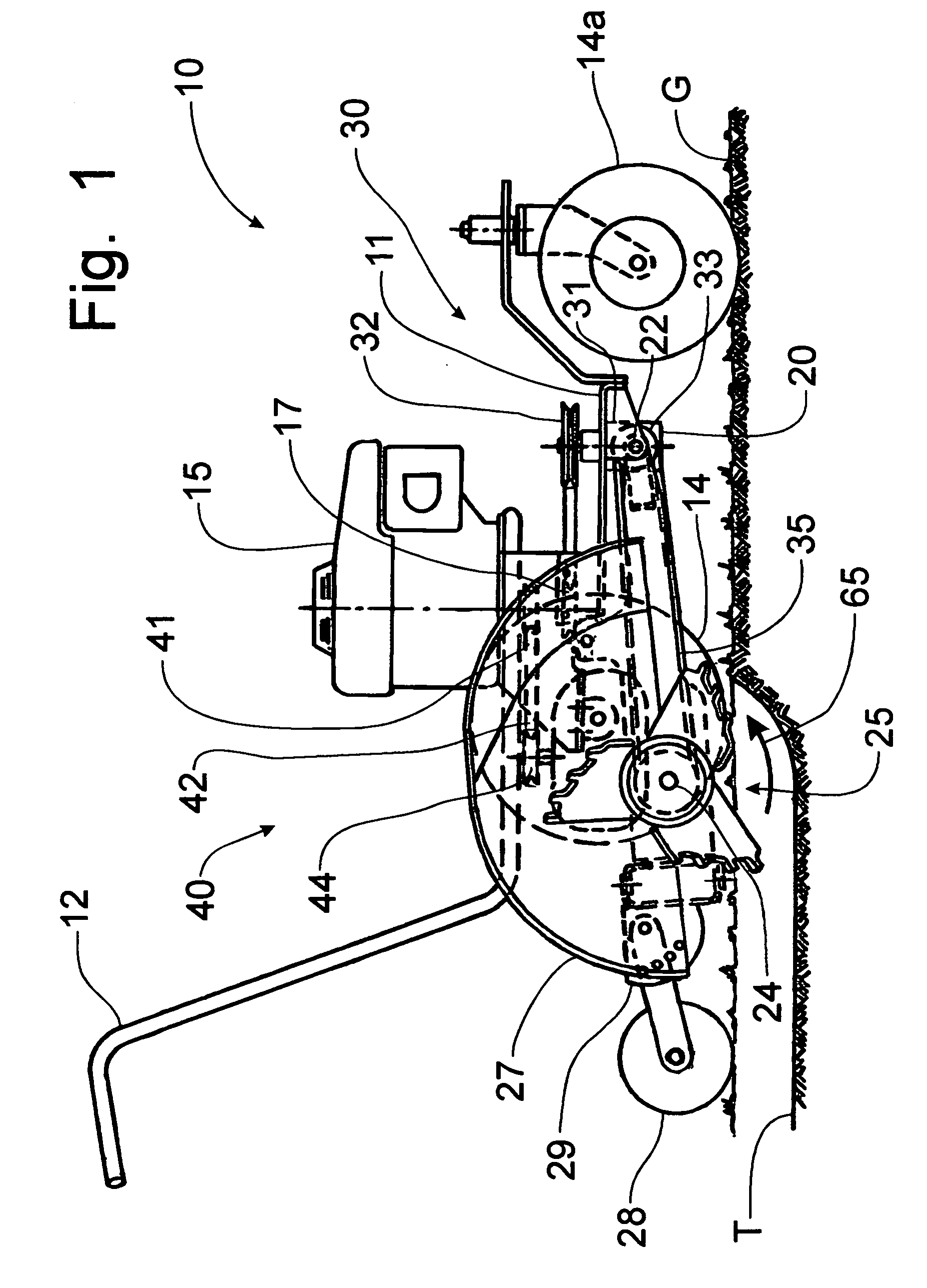
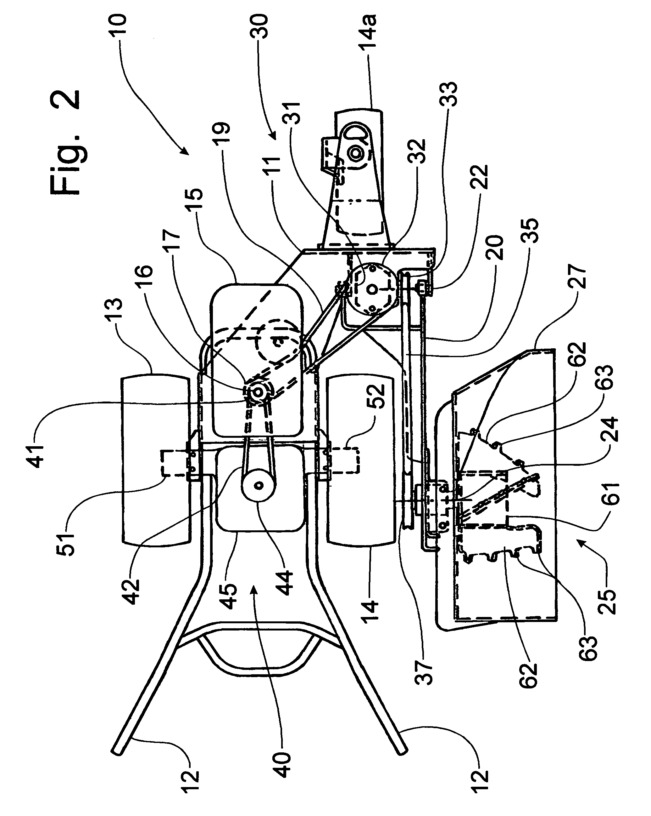
[0029]Referring now to FIGS. 1 and 2, a walk-behind version of a landscape edging / trenching implement incorporating the principles of the instant invention can best be seen. Any left or right references are used as a matter of convenience and are determined by standing at the rear of the machine where the operator would walk gripping the handlebars to effect movement of the implement in a forward direction. One skilled in the art will readily recognize that the principles of the instant invention can be applied to self-propelled or mounted versions of powered implements as well as to walk-behind versions; however, only the walk-behind version, as depicted in the drawings, will be described to exemplify the inventions.

[0030]A edging / trenching implement 10 is known in the art for forming a small shaped trench in the surface of the ground to bury utility lines of various kinds, such as water, gas, electrical, communications cables, sewer lines and dog fencing, and to shape the edges of...


PUM


Abstract

A walk-behind trenching implement has a side mounted rotary trenching tool for creating a profiled trench into the surface of the earth, which can also be used as an implement to edge landscape beds. The trenching implement is powered by an engine that delivers rotational power in an unbalanced manner to the wheel adjacent to the rotatable trenching tool. The wheel opposite to the trenching tool is can be non-powered to freely rotate as the implement is moved across the surface of the ground, or braked to unbalance power delivery through a differential. This unbalanced propulsion drive induces a skewing action into the operation of the implement that counterbalances the opposite skewing action resulting from the operation of the trenching tool to provide a more smoothly operating implement. A trenching tool having a configuration conducive to profile modification allows flexibility in the desired shape of the trench being formed.

Description

BACKGROUND OF THE INVENTION[0001]This invention relates generally to a powered utility apparatus and, more particularly, to a powered trenching apparatus that can operated from behind the implement.[0002]Powered walk behind or self-propelled tools are known in the art. Examples include brush mowers, lawn mowers, rotary brooms, string trimmers and edging mechanisms. Each such implement is operably driven by a dedicated power unit. Motive power is transferred from the power unit to the drive wheels, while other power drive trains transfers operational power to the work apparatus, such as an edging mechanism. Many of these powered walk behind implements have the work apparatus positioned generally centrally and likely forwardly of the engine to provide a balanced load to the operation of the implement. Some such powered implements, like the edging mechanism for example, position the work apparatus to one side of the implement. Edging mechanisms, however, do not encounter a significant ...

Claims


Application Information

Patent Timeline
IPC IPC(8): A01G3/00A01G3/06A01B33/02A01B33/00
CPCA01G3/062A01B33/028
Inventor TEMPLETON, DAVID J.
Owner TURF TEQ
Learn More