Apparatus for making permanent hardline connection

a technology of hardline connection and apparatus, which is applied in the direction of coupling device connection, coupling device base/case, two-part coupling device, etc., can solve the problem of not being able to prevent radiation leakage as effectively, adding to the difficulty of properly interconnecting the cable, and making the job of technicians using threaded connectors even more difficul

Inactive Publication Date: 2005-04-26
PPC BROADBAND INC
View PDF26 Cites 251 Cited by
  • Summary
  • Abstract
  • Description
  • Claims
  • Application Information

AI Technical Summary

Problems solved by technology

The principal difference between hard-line and drop cables, apart from the size of the cables, is that hard-line cables include a rigid or semi-rigid outer conductor, typically covered with a weather protective jacket, that effectively prevents radiation leakage and protects the inner conductor and dielectric, while drop connectors include a relatively flexible outer conductor, typically braided, that permits their bending around obstacles between the transition or junction box and the location of the device to which the signal is being carried, i.e., a television, computer, and the like, but that is not as effective at preventing radiation leakage.
Hence, by repeatedly shortening the effective length of the transmission cable due to the severing required to detach the cable from the port, additional parts, such as extenders, must be employed which add to the difficulty of properly interconnecting the cable.
It also is difficult to fit a wrench into the space provided by many equipment ports, thereby making the technician's job that uses threaded connectors even more difficult.
While such connectors eliminate the difficulties associated with the threaded connectors, the crimping action often produces inconsistent electrical connection between the connector and the cable, also degrading the cable's outer conductor, thereby creating signal losses that ultimately reduce the quality of the signal being transmitted.
A compression tool that slides the compression body into the connector is utilized by the technician to effect the connection, and due to the physical constraints of the compression member and connector body, it is impossible for the technician to use too much force to effect the interconnection.

Method used


Image

  • Apparatus for making permanent hardline connection
  • Apparatus for making permanent hardline connection
  • Apparatus for making permanent hardline connection

Examples


first embodiment

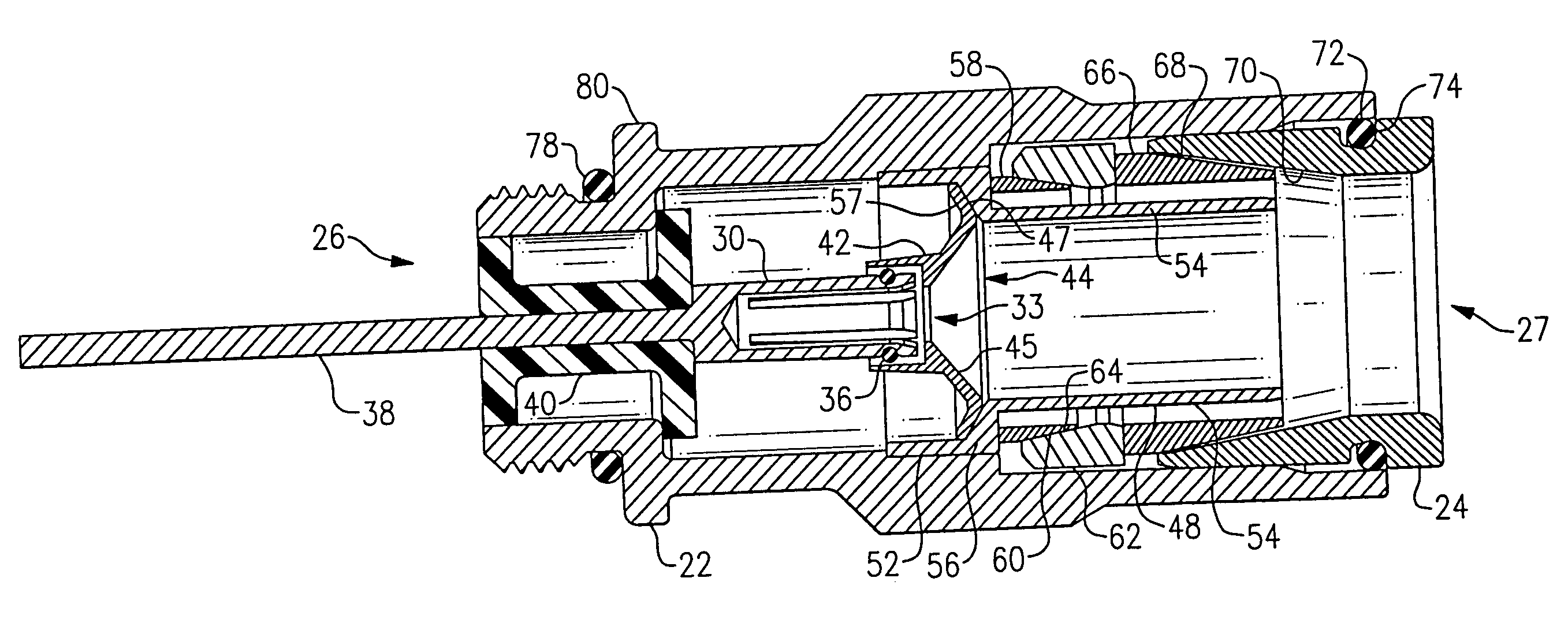
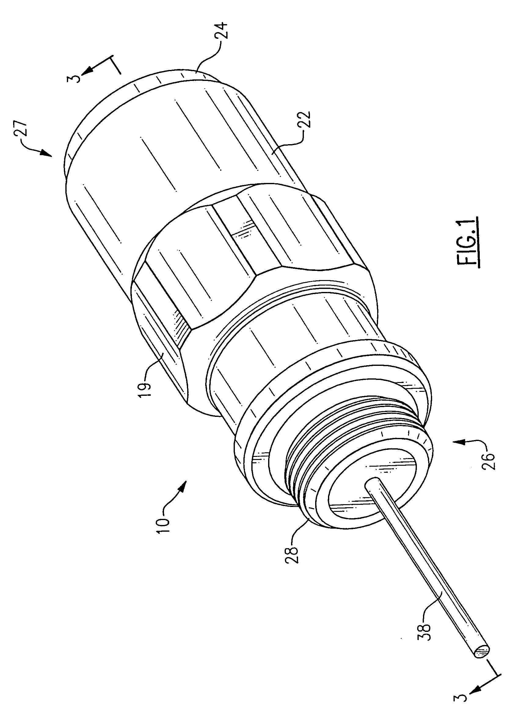
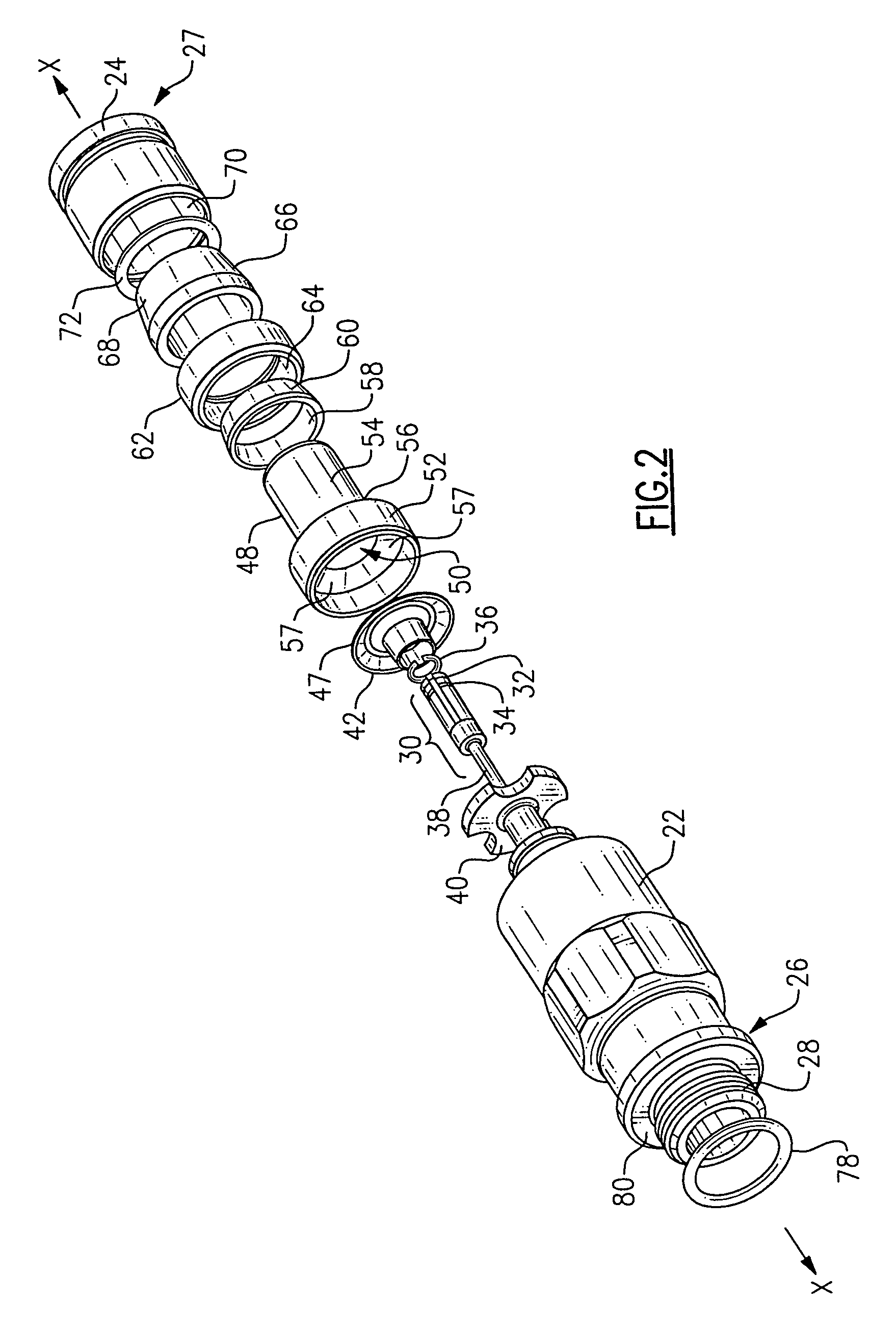
[0036]Referring now to the drawings, wherein like reference numerals refer to like parts throughout, and especially to FIGS. 1 and 5C, a connector 10 interconnects a hard-line coaxial cable 12 to an equipment port 14. Hard-line coaxial cable 12 generally includes a central conductor 16 for carrying a signal, such as a CATV signal, a layer of dielectric material 18 covering central conductor 16, and an outer conductive member 20 composed of conventional hard-line material spaced from central conductor 16 by dielectric 18. A jacket 21 may coat outer conductor 20 to protect it from the weather. Equipment port 14 may be any conventional type of port in which signal processing / conditioning equipment is stored and to which hard-line cables are traditionally interconnected, such as, for example, a tap, amplifier, filter, trap, or the like. Hard-line coaxial cables are typically used as transmission lines in a CATV system, or the like.

[0037]Connector 10 includes a connector body 22 preferab...

second embodiment

[0045]Referring to FIG. 6, the present invention is shown as a pin connector 100 used in connection with QR cable. Pin connector 100 is functionally equivalent to connector 10, and includes many of the same components as used with connector 10, all of which are referenced by identical reference numerals, while those components that are modified are given new reference numerals. When using standard QR type cable, most of the cable jacket is left on the cable, with only a little of the jacket being cut back during installation. Only RF seal 58 makes electrical contact with the ground braid of the QR cable, with subsequent electrical contact being made through RF seal driver 62 and connector body 22. In this embodiment, clamping / sealing member 66 only contacts the outer sheath of the QR cable.

[0046]Pin connector 100, extending along a longitudinal axis X, includes a connector body 102 and a press fit compression body 104 that axially slides relative to connector body 102 between first ...

third embodiment

[0048]Referring to FIG., the invention is shown as a pin connector in the closed position. A connector 130 includes a front body 132 and a back body 134. A conductive pin 136 is held within front body 132 by an insulator 137. Conductive pin 136 is electrically connected to a contact 138 which in turn is electrically connected to a collet 140. Preferably, conductive pin 136, contact 138, and collet 140 are one-piece. A plurality of teeth 142 are on an inner surface of collet 140 to provide an enhanced interference fit with the center conductor of the cable upon installation. For ease of manufacturing, teeth 142 are preferably formed as in internal threaded portion of collet 140. Portions of a mandrel 144 fit inside both front body 132 and back body 134. The portion of mandrel 144 inside front body 132 is preferably press fit inside front body 132. Mandrel 144 is preferably plastic. Mandrel 144 includes a seizing portion 146 which presses teeth 142 onto the central conductor of the ca...


PUM


Abstract

A permanent connector interconnects a hard-line coaxial cable to a connection housing. A contact is interconnected with and extends coaxially through a connector body. A collet one-piece with the contact receives a central conductor of the coaxial cable, while a sealing member and mandrel receive an outer conductor of the coaxial cable between them. A compression body positioned radially adjacent a portion of the connector body moves axially between first and second positions, wherein when the compression body is in its first position, the coaxial cable is removable from within the connector, and when the compression body is in its second position, the coaxial cable is not removable from within the connector. The compression body acts indirectly upon the sealing member so that an electrical connection is made between the sealing member and the outer conductor of the cable when the compression body is in its second position.

Description

FIELD OF THE INVENTION[0001]The present invention relates generally to coaxial cable connectors, and more particularly to such connectors used with hard-line coaxial cables.BACKGROUND OF THE INVENTION[0002]Coaxial cable is a typical transmission medium used in communications networks, such as a CATV network. The cables which make up the transmission portion of the network are typically of the “hard-line” type, while those used to distribute the signals into residences and businesses are typically “drop” connectors. The principal difference between hard-line and drop cables, apart from the size of the cables, is that hard-line cables include a rigid or semi-rigid outer conductor, typically covered with a weather protective jacket, that effectively prevents radiation leakage and protects the inner conductor and dielectric, while drop connectors include a relatively flexible outer conductor, typically braided, that permits their bending around obstacles between the transition or juncti...

Claims


Application Information

Patent Timeline
Patent Type & Authority Patents(United States)
IPC IPC(8): H01R9/05H01R13/00H01R13/646H01R13/52
CPCH01R9/0518H01R9/0524H01R24/40H01R2103/00H01R13/5221
Inventor MONTENA, NOAH
Owner PPC BROADBAND INC
Why Eureka
Try Eureka