
Battery pack

Inactive Publication Date: 2005-04-26
PANASONIC CORP
View PDF8 Cites 41 Cited by
  • Summary
  • Abstract
  • Description
  • Claims
  • Application Information

AI Technical Summary

Benefits of technology

[0009]An object of the invention is to provide a battery pack that can cope with various storage space shapes by forming a space between a plurality of batteries for heat radiation and the enhancement of the rigidity of the battery pack.
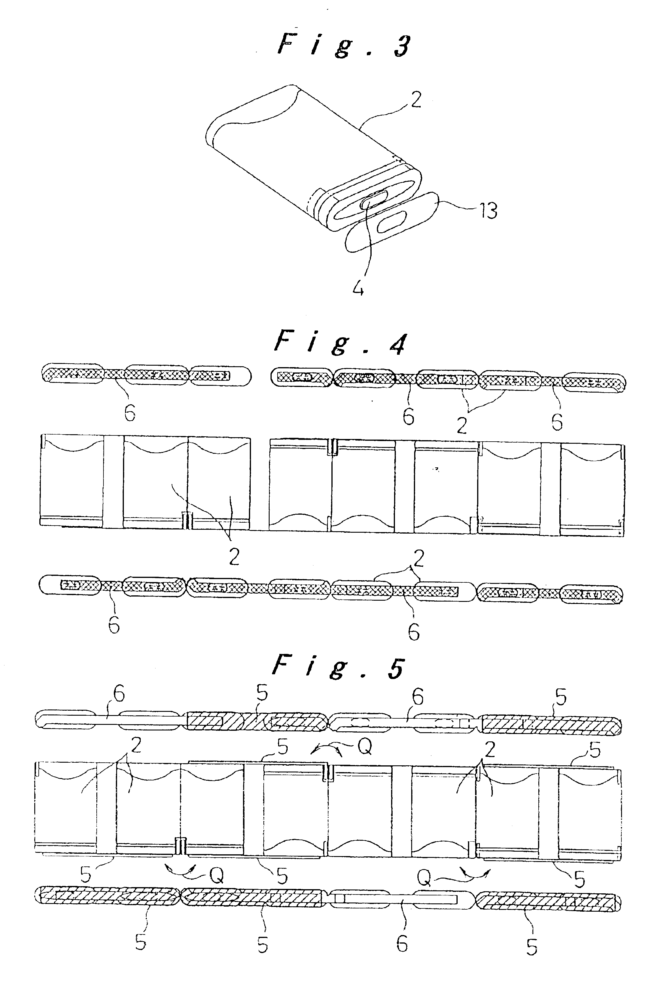
[0010]In the battery pack according to the present invention for achieving the object described above, a plurality of secondary batteries are electrically connected, and are disposed in parallel with a predetermined spacing. Surfaces where electrode terminals of the secondary batteries are provided are connected with electrical insulating plates. As described above, the secondary batteries are connected by the electrical insulating plates, and at the same time the batteries are disposed in parallel with a predetermined spacing. By repeating this arrangement any number of times in the parallel direction, the plurality of batteries are disposed in parallel with a spacing and are unitized. Thereby a good heat radiation capability is provided, and a force compressing the secondary batteries is prevented from being applied by arranging supporting bodies such as supporting struts and the like in the spacing.
[0012]Also, because each electrode terminal of the secondary batteries is connected with metal plates, and the electrical insulating plates are adhered on the metal plates, electrical and mechanical connections are made at the same positions. Also the metal plates that are thin and have a low mechanical strength can be protected by the electrical insulating plates.
[0015]The arrangement of the plurality of secondary batteries is made to correspond to the shape of the storage space for secondary batteries. Also, the arrangement of the batteries in which they are disposed in parallel as well as the number of batteries to be disposed in the layout is selectively combined depending on the shape of the storage space. In this way, the secondary batteries have a high degree of freedom of arrangement.
[0017]Furthermore, by binding connected or joined secondary batteries, disposed in parallel, with an adhesive tape, the unitized structure of a plurality of connected or joined secondary batteries can be strengthened.

Problems solved by technology

However, a secondary battery produces heat while charging and discharging, and even a little amount of heat is not sufficiently radiated when a plurality of secondary batteries are disposed in a state in which they are in close contact with each other.
As a result, in a closed space in a pack case, the temperature of the batteries rises which affects the charging-discharging characteristics of the batteries.
However, because the spacer 43 is not a connecting element, connection strength sufficient to connect any number of batteries with a flat shape cannot be obtained.
Also, the battery pack storage space in equipment is not always of a rectangular shape.

Method used


Image

  • Battery pack
  • Battery pack
  • Battery pack

Examples


Embodiment Construction

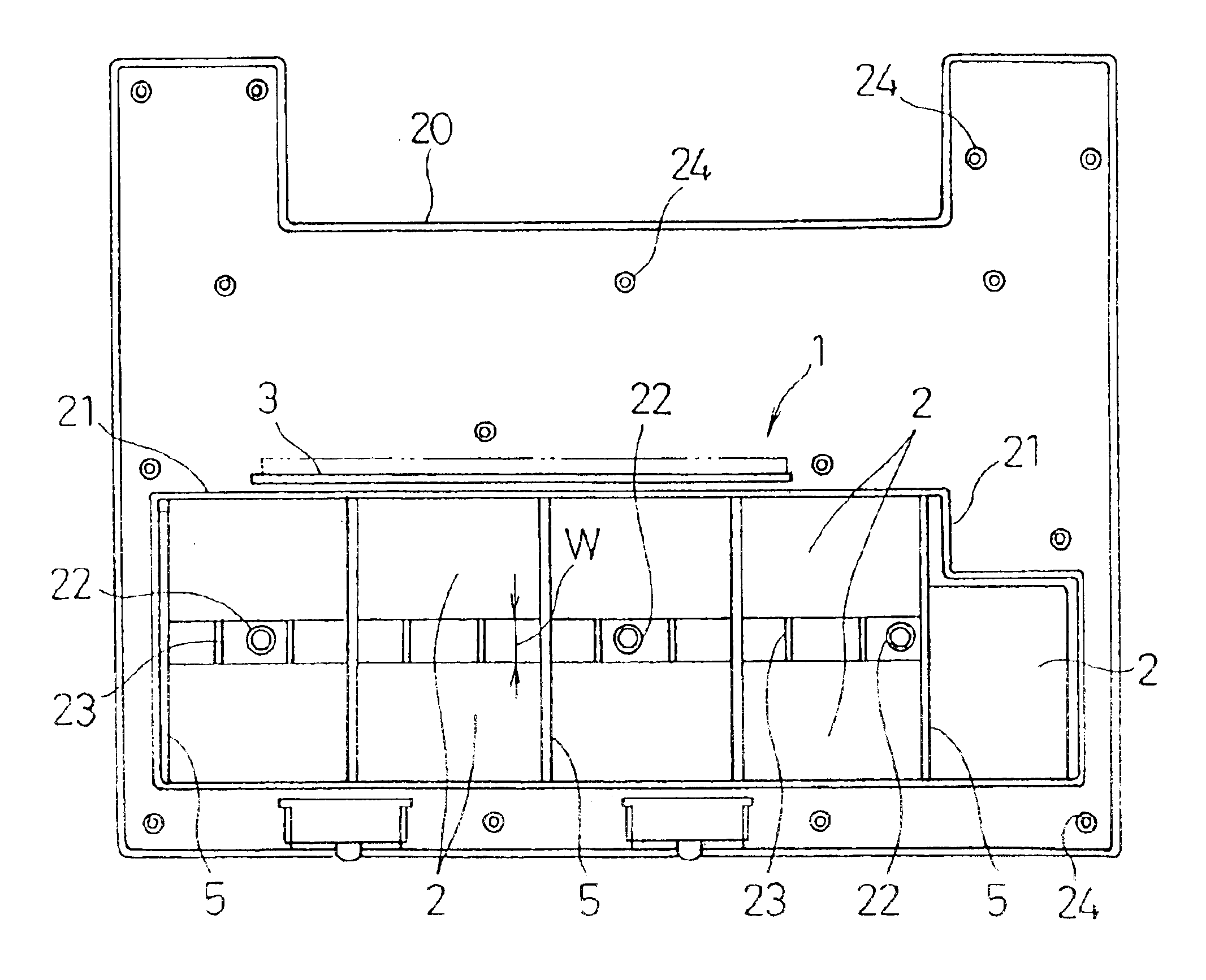
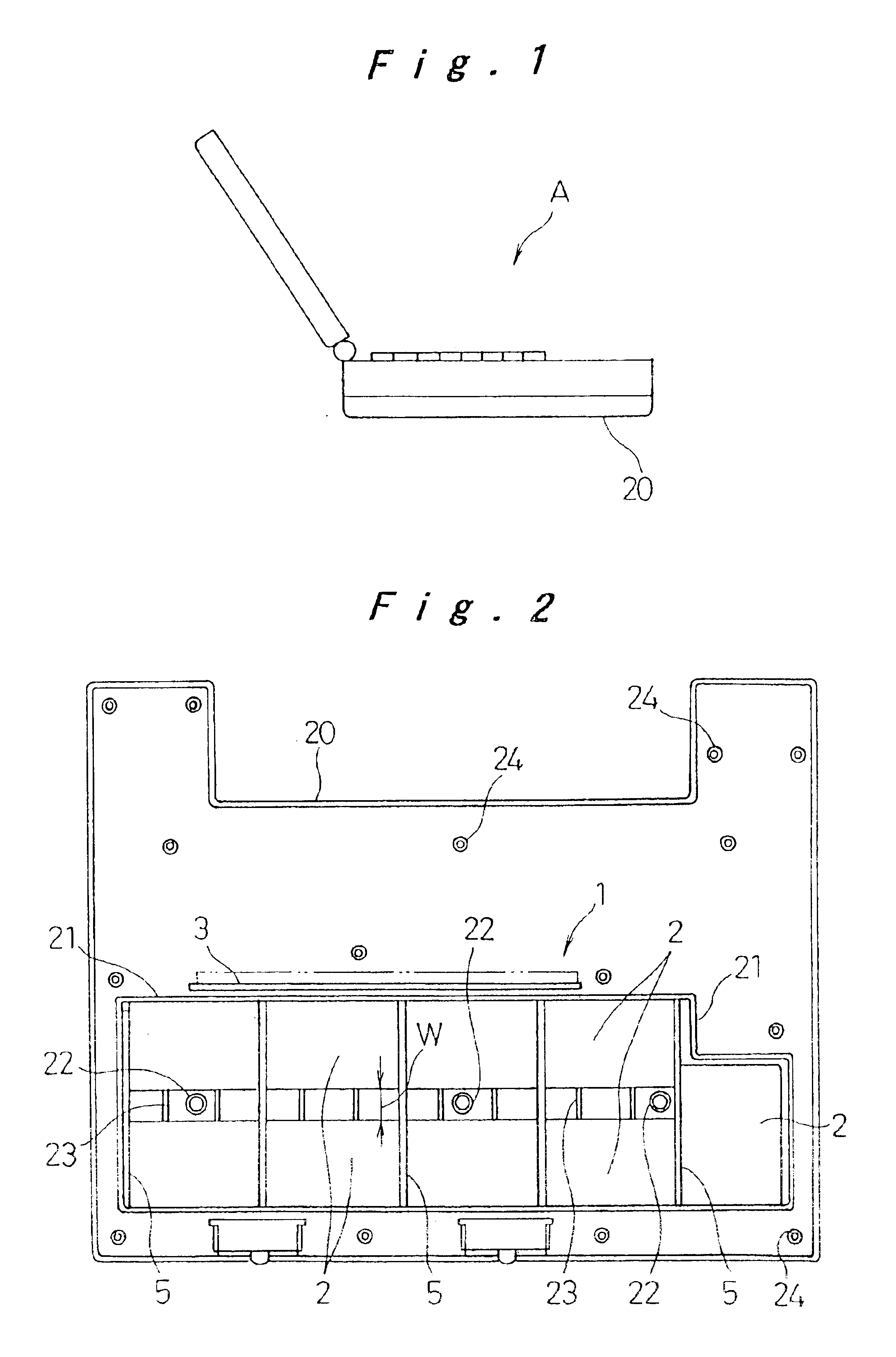
[0031]The embodiment of the present invention describes a battery pack adapted for a battery power source for a notebook computer. As shown in FIG. 1, the battery pack is formed in a shape that can be stored in a battery storage space within an additional case 20 detachably mounted at the bottom surface of a notebook computer A.

[0032]FIG. 2 is a plan view showing a state in which a battery pack 1 relating to the present invention is stored within the additional case 20, and, in the figure, the additional case 20 is in a state in which a cover to be fixed over the shown plane is removed. The cover is formed in a plate-like shape, and is fixed with screws to a plurality of bosses 24 with internally threaded elements inserted therein. The battery pack 1 is provided with nine secondary batteries stored in a battery storage frame 21 formed in the additional case 20, and with a circuit board 3 constituting a battery protection circuit, circuits for communicating with the notebook computer...


PUM


Abstract

A plurality of secondary batteries are connected either one of in series or in parallel with metal plates, and are joined by connection plates to form a unit with spacing provided between the secondary batteries disposed in parallel. Also, when arranging an odd number of the secondary batteries, an arrangement is also possible where a connection plate at an end point of an even number of the secondary batteries is joined to the remaining battery so that the secondary batteries can be arranged in a different shape. The spacing improves the heat radiation capability of the secondary batteries, and a pressing force is prevented from being applied to the secondary batteries by forming supporting struts in the spacing.

Description

[0001]The present disclosure relates to subject matter contained in priority Japanese Patent Application No. 2000-262154, filed on Aug. 31, 2000, the contents of which is herein expressly incorporated by reference in its entirety.BACKGROUND OF THE INVENTION[0002]1. Technical Field of the Invention[0003]The present invention relates to a battery pack used as a power source for portable equipment such as notebook-sized personal computers (hereafter referred to as “notebook computers”), portable information terminal equipment, and the like. More specifically, the present invention relates to a battery pack in which a heat radiation capability and a resistance to a pressing force are taken into consideration.[0004]2. Description of Related Art[0005]When a high voltage-output or a high battery capacity is required for a battery as a power source for portable equipment, a battery pack is formed with a plurality of secondary batteries connected either one of in series and in parallel. The ...

Claims


Application Information

Patent Timeline
IPC IPC(8): H01M2/10H01M2/22H01M10/00H01M2/02H01M2/20H01M6/42H01M10/42H01M50/103H01M50/209H01M50/503H01M50/528
CPCH01M2/0207H01M2/1061H01M2/204H01M10/425H01M2/022H01M2/105H01M6/42H01M10/5073H01M10/5004H01M10/5012H01M10/5028H01M10/5046H01M10/0525H01M10/64H01M10/6551H01M10/623H01M10/6566H01M10/613Y02E60/10H01M50/107H01M50/213H01M50/209H01M50/103H01M50/503
Inventor CHIKADA, TATSUHISA
Owner PANASONIC CORP
Learn More