Electromagnetic compliant shield having electrostatic discharge protection

a shield and electrostatic discharge technology, applied in the direction of optical elements, coupling device connections, instruments, etc., can solve the problems of affecting the normal operation of other components and circuitry in the system, damage to system components, and failure of components within the housing

Active Publication Date: 2005-04-26
CIENA
View PDF11 Cites 25 Cited by
  • Summary
  • Abstract
  • Description
  • Claims
  • Application Information

AI Technical Summary

Problems solved by technology

These components can generate electromagnetic interference (EMI), which interrupts the normal operation of other components and circuitry in the system.
Electrostatic energy can also be created, which, if not discharged to ground path directly, can damage system components.
The heat can cause the failure of components within the housing.

Method used


Image

  • Electromagnetic compliant shield having electrostatic discharge protection
  • Electromagnetic compliant shield having electrostatic discharge protection
  • Electromagnetic compliant shield having electrostatic discharge protection

Examples


Embodiment Construction

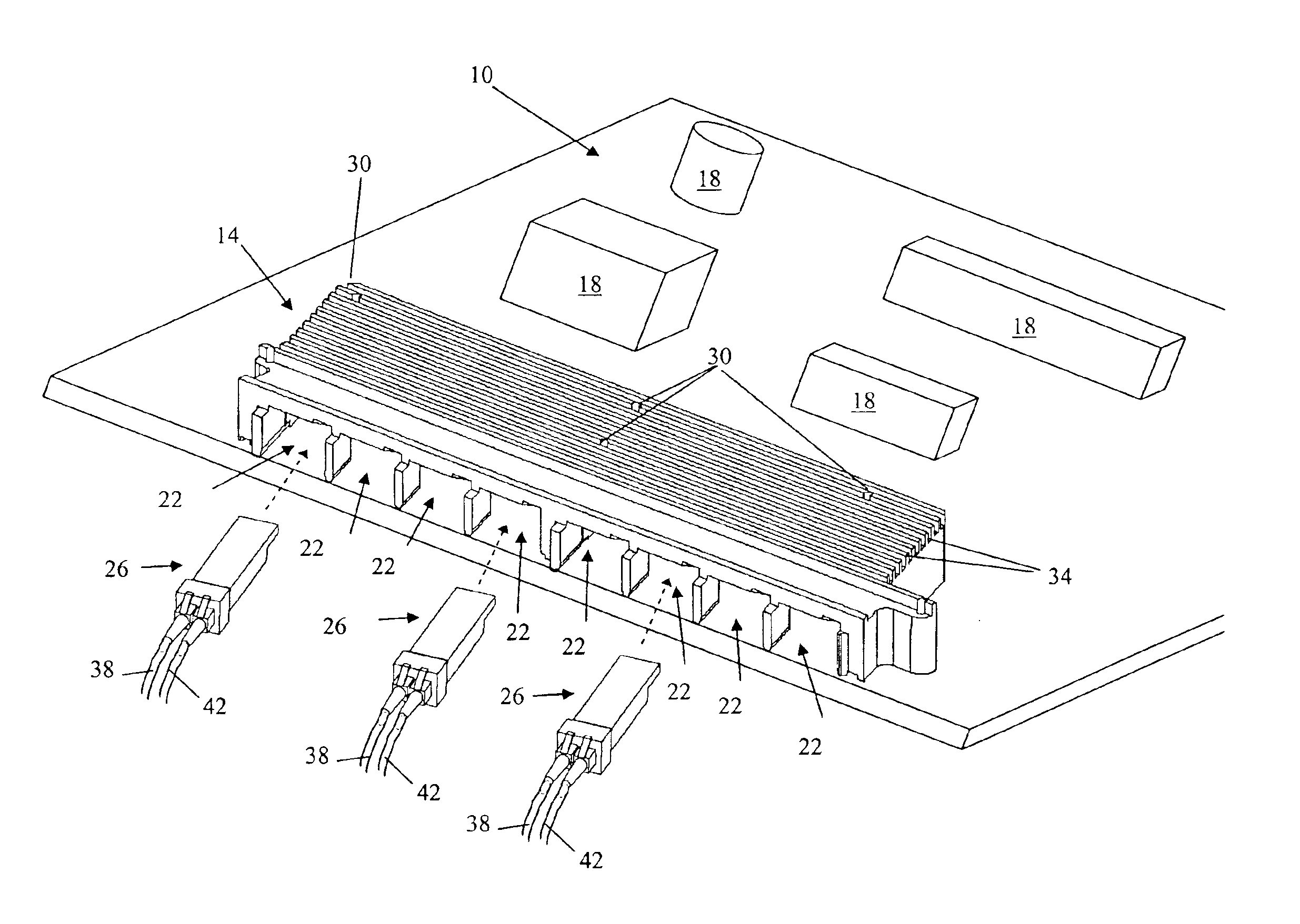
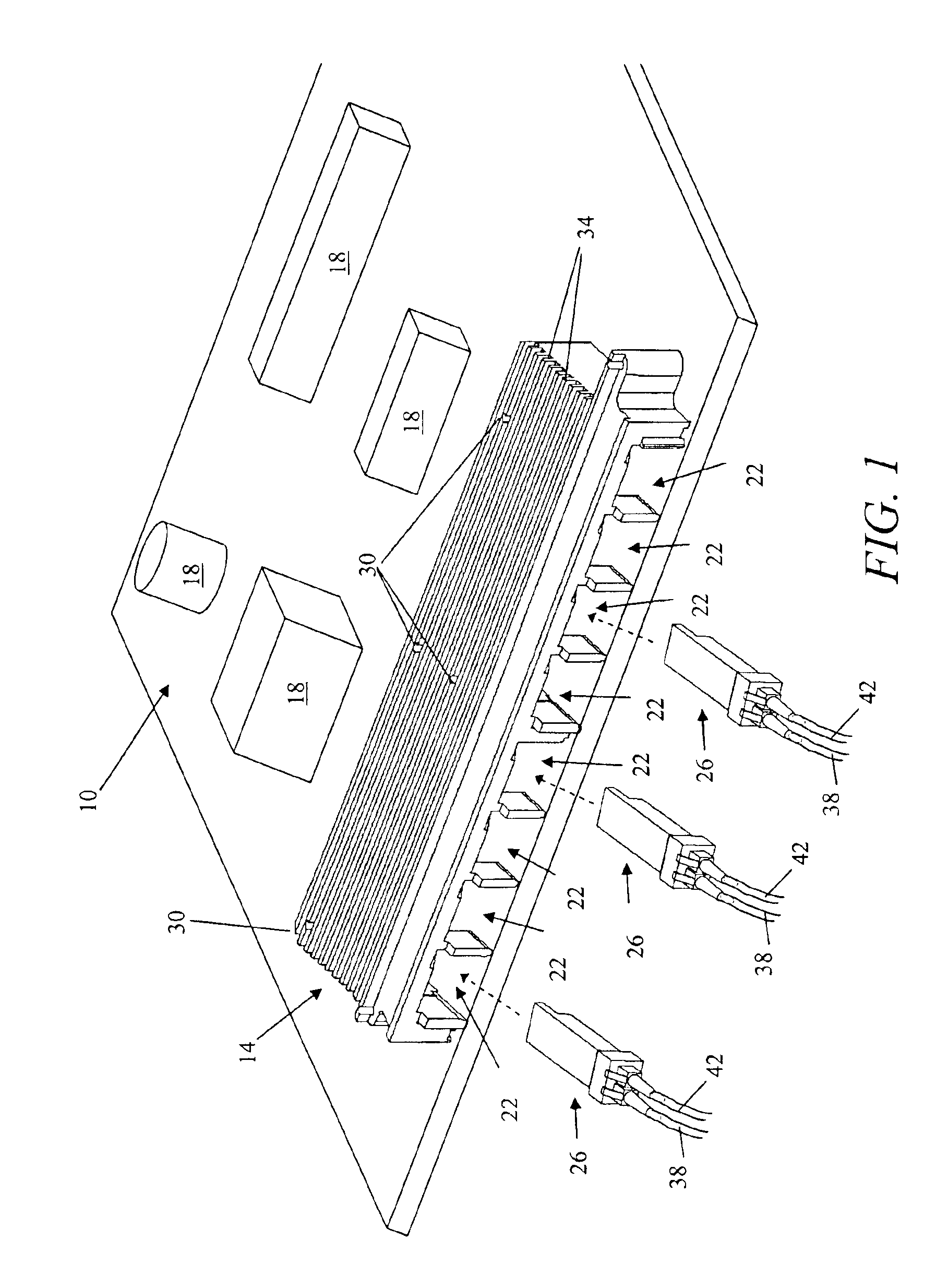
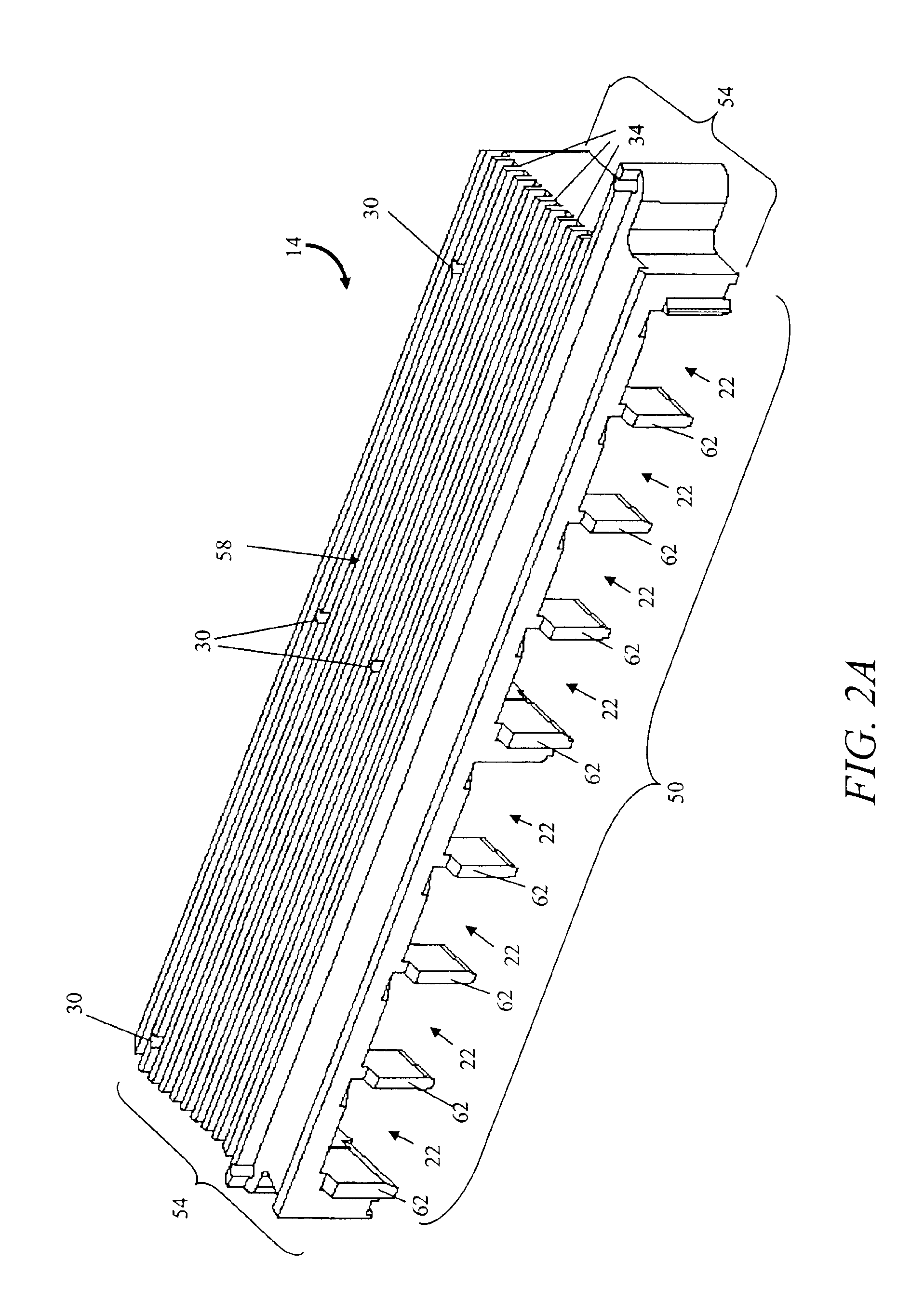
[0013]With reference to FIG. 1, a printed circuit board (PCB) includes an electromagnetic compliant (EMC) shield, or housing, 14 (i.e., an enclosure) and a plurality of electrical components 18. The shield 14 includes a plurality of openings 22 each configured to receive an electronics module 26, a plurality of bores 30, and a plurality of fins 34 for heat dissipation. The number of fins 34 can vary according to the specific application of the PCB and the heat load generated by the enclosed electronics modules 26.

[0014]The shield 14 is mounted to the PCB 10 by fasteners extending through the bores 30. For example, the shield 14 is mounted to the PCB 10 by screws that engage threaded openings in the PCB 10.

[0015]The electronics modules 26 are inserted into respective openings 22 in the shield 14 and are in electrical communication with the various components 18 through traces on the PCB 10. In the illustrated embodiment, each electronics modules 26 is a small form factor pluggable op...


PUM


Abstract

An electromagnetic compliant (EMC) shield for shielding electronic components on a circuit board from electromagnetic energy generated by electronics modules inside the EMC shield. The shield also contains electromagnetic energy generated by the electronic components on the circuit board from escaping to outside the EMC shield. The EMC shield includes a first side and a second side. The first side has a plurality of openings. Each of the openings is configured to receive a respective electronics module. The second side has a bottom edge with a groove to receive a conductive gasket. The first and second sides extend normal to the circuit board when the EMC shield is mounted to the circuit board.

Description

FIELD OF THE INVENTION[0001]The invention relates generally to electromagnetic compliant enclosures and more specifically to electromagnetic compliant shields with heat sinking capability.BACKGROUND[0002]Data rates in communications systems continue to increase. As a result, there is a shift from purely electrical systems to optical systems and to combinations of optical and electrical systems. In combined systems, there are both electrical and optical components. These systems include components, such as laser transmitters and optical detector circuitry, to transform optical signals to electrical signals and / or electrical signals to optical signals. These components can generate electromagnetic interference (EMI), which interrupts the normal operation of other components and circuitry in the system. Electrostatic energy can also be created, which, if not discharged to ground path directly, can damage system components.[0003]In many systems, the electrical and optical components are...

Claims


Application Information

Patent Timeline
Patent Type & Authority Patents(United States)
IPC IPC(8): H05K9/00G02B6/38H01R12/16H01R13/648
CPCG02B6/3897G02B6/4277H05K9/0058H01R13/6485H01R23/6873H01R13/6594
Inventor MISTRY, BALWANTRAISONDEREGGER, MARK
Owner CIENA
Why Eureka
Try Eureka