

Induction devices with distributed air gaps
- Summary
- Abstract
- Description
- Claims
- Application Information
AI Technical Summary
Benefits of technology
Problems solved by technology
Method used
Image

Examples
Embodiment Construction
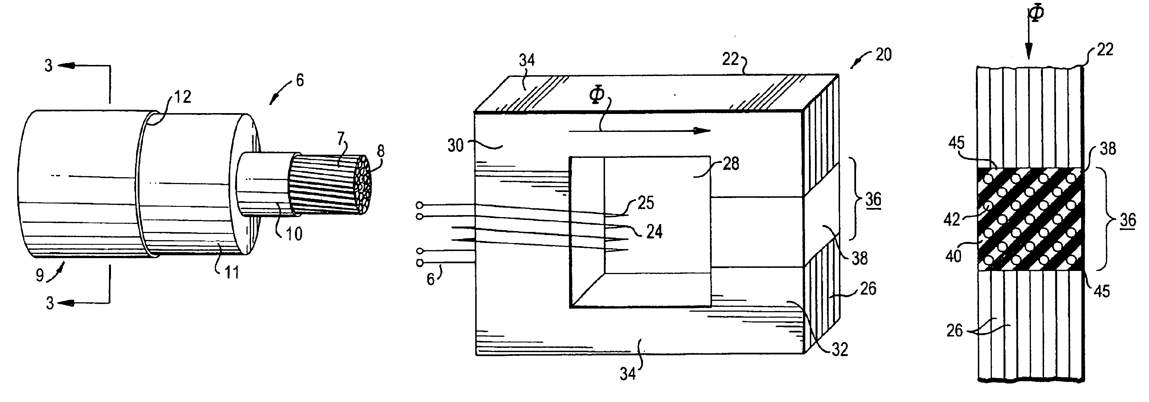
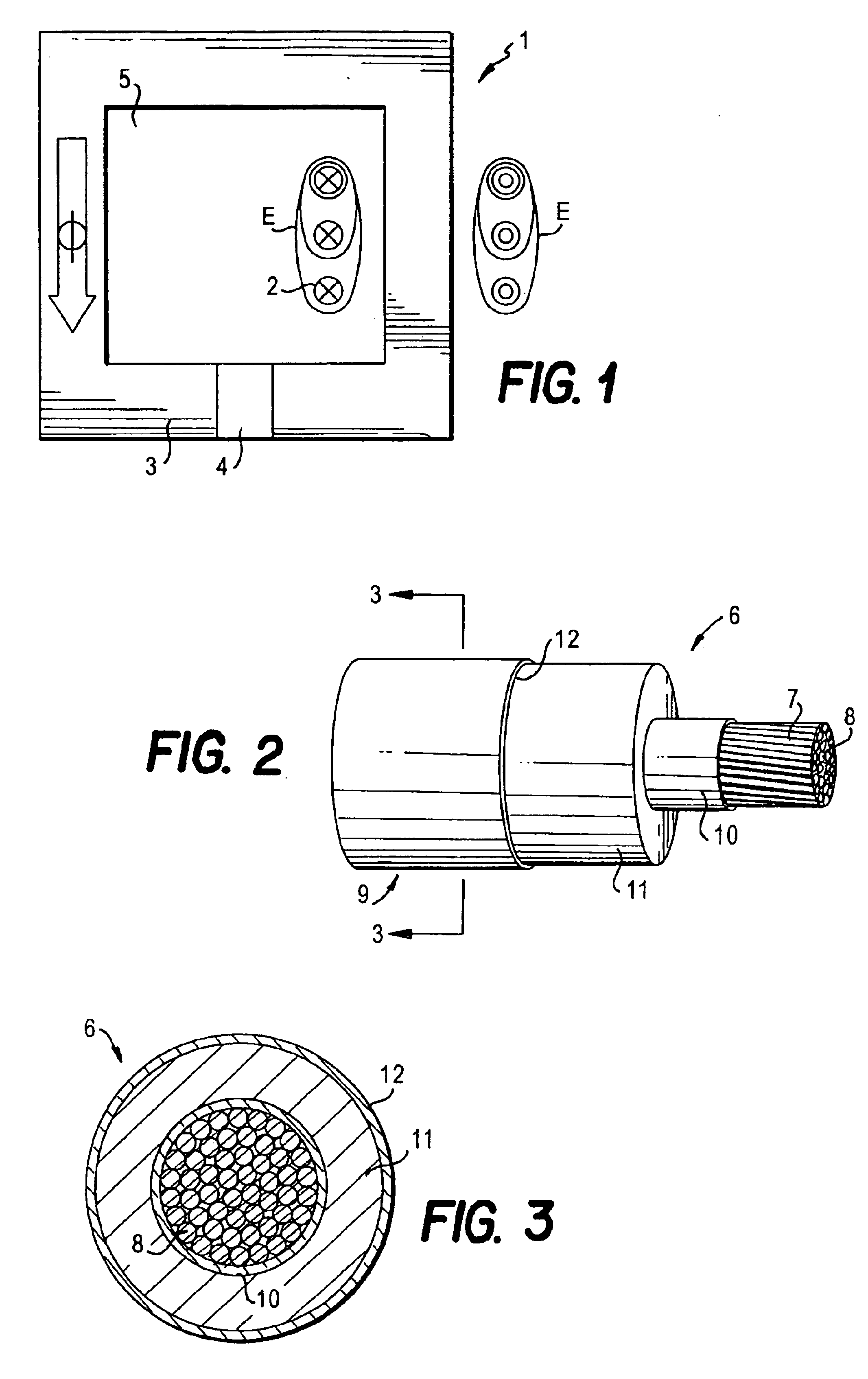
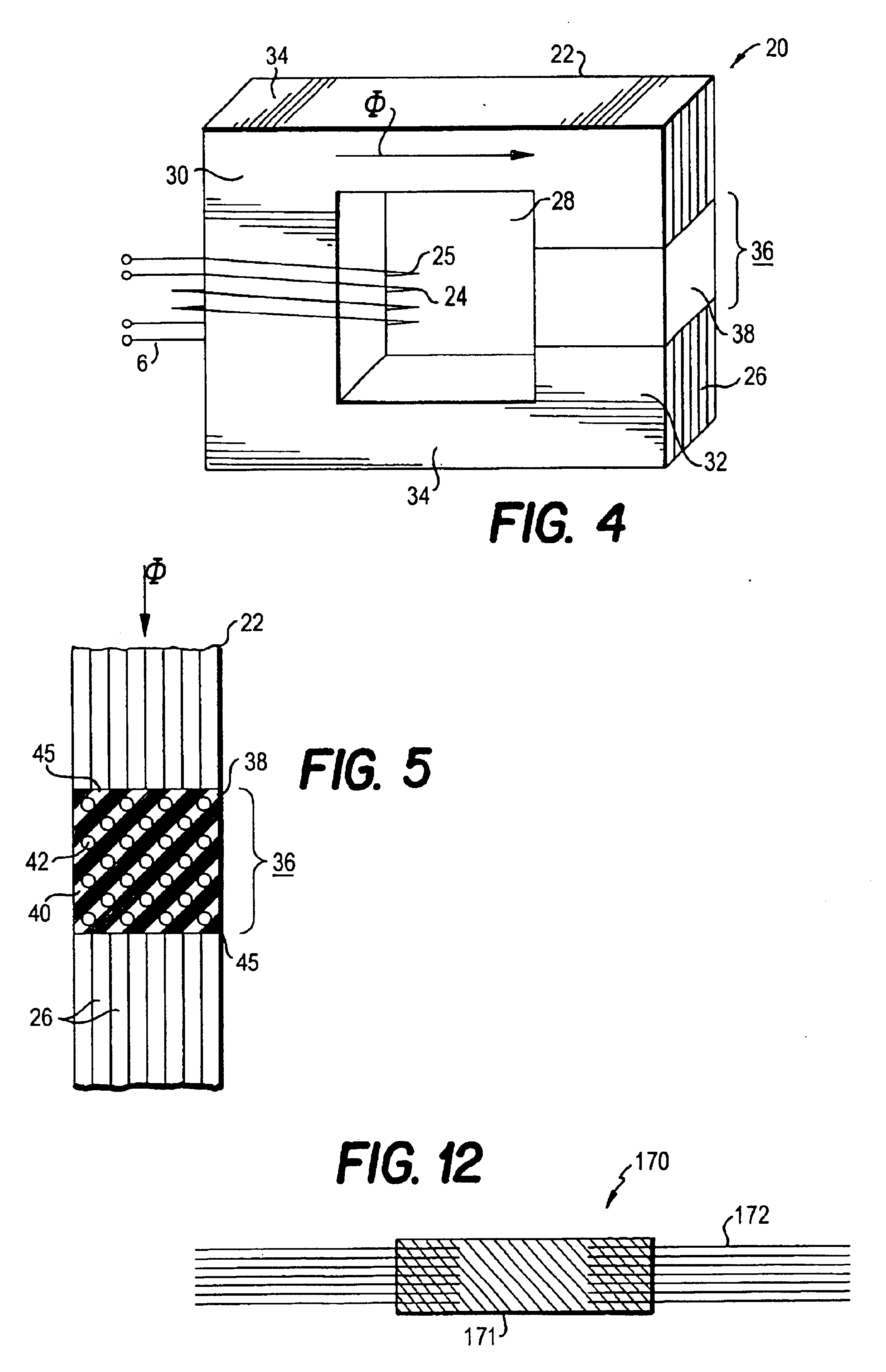
[0043]The present invention will now be described in greater detail with reference to the accompanying drawings. FIG. 1 shows a simplified view of the electric field distribution around a winding of a induction device such as a power transformer or reactor 1 which includes one or more windings 2 and a core 3. Equipotential lines E show where the electric field has the same magnitude. The lower part of the winding is assumed to be an earth potential. The core 3 has a distributed air gap 4 according to the invention and a window 5. The core may be formed of a laminated sheet of magnetically permeable material, e.g. silicon steel, or may be formed of magnetic wire, ribbon or powder metallurgy material. The direction of the flux φ is shown by the arrow. In general, the flux φ confined or nearly confined within the core 3 is uninterrupted as shown.
[0044]The potential distribution determines the composition of the insulation system, especially in high power systems, because it is necessar...
PUM
 Abstract
Description
Claims
Application Information