
Actively reconfigurable pixelized antenna systems

a pixelized antenna and active reconfiguration technology, applied in the direction of individual energised antenna arrays, resonant antennas, radiating element structural forms, etc., can solve the problems of large number of small and cheap rf switches, large number of switches demonstrated so far, and high complexity of conventional control of such active elements, etc., to achieve low cost control, flexible

Inactive Publication Date: 2005-04-26
PENN STATE RES FOUND
View PDF21 Cites 34 Cited by
  • Summary
  • Abstract
  • Description
  • Claims
  • Application Information

AI Technical Summary

Benefits of technology

[0008]The present invention provides efficient, flexible, and low-cost control for large numbers of antenna pixel tunable elements using approaches analogous to those used in liquid crystal displays.

Problems solved by technology

However, control of such active elements conventionally involves a high degree of complexity.
For low-cost, light-weight, and thin antennas, and particularly for antenna designs requiring many elements, this requires a large number of small and cheap RF switches.
Although there has been some success in using microelectromechanical system (MEMS) approaches to fabricate small RF switches, the switches demonstrated thus far are expensive and often have relatively poor RF and / or reliability characteristics.

Method used


Image

  • Actively reconfigurable pixelized antenna systems
  • Actively reconfigurable pixelized antenna systems
  • Actively reconfigurable pixelized antenna systems

Examples


Embodiment Construction

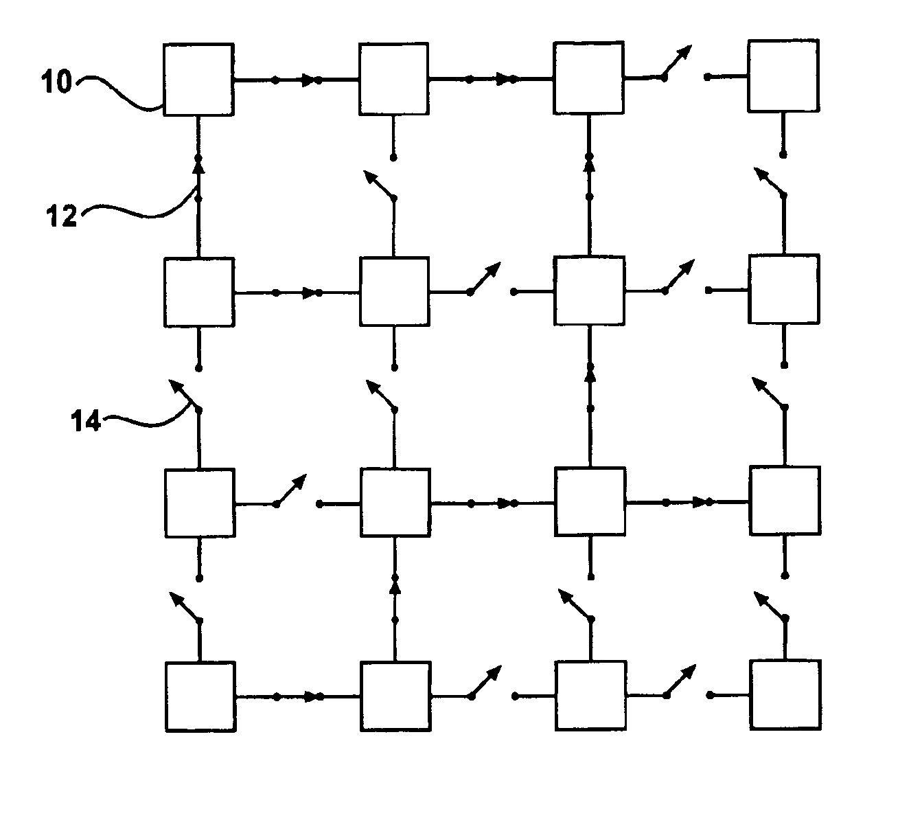
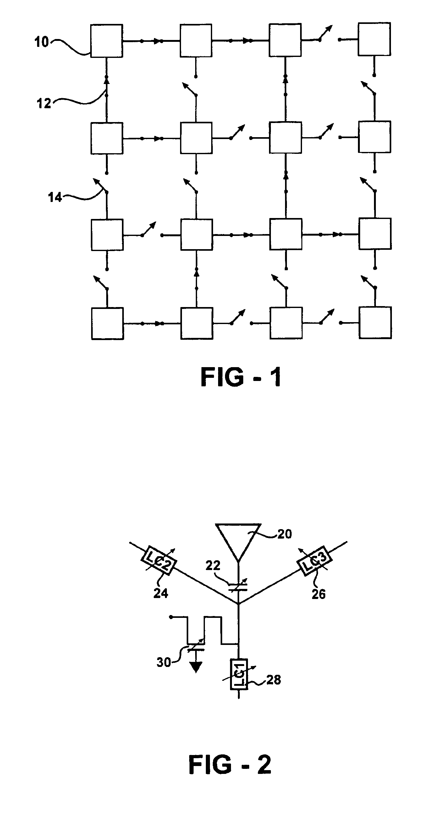
[0017]FIG. 1 shows an antenna pixel 10, interconnected to other antenna pixels through interconnections such as 12, illustrated in the form of a closed switch. The electrical control of tunable elements, discussed in more detail below, allows pixel interconnections to be effectively removed, for example as shown in the form of an open switch at 14. The figure provides a schematic of a generalized reconfigurable antenna using switches to interconnect a (possibly large) number of antenna elements. Such an antenna can have a single or multiple RF feed-points (using single or multiple phases) and the antenna characteristics can be adjusted and controlled by varying the state of the switches that interconnect individual antenna elements.

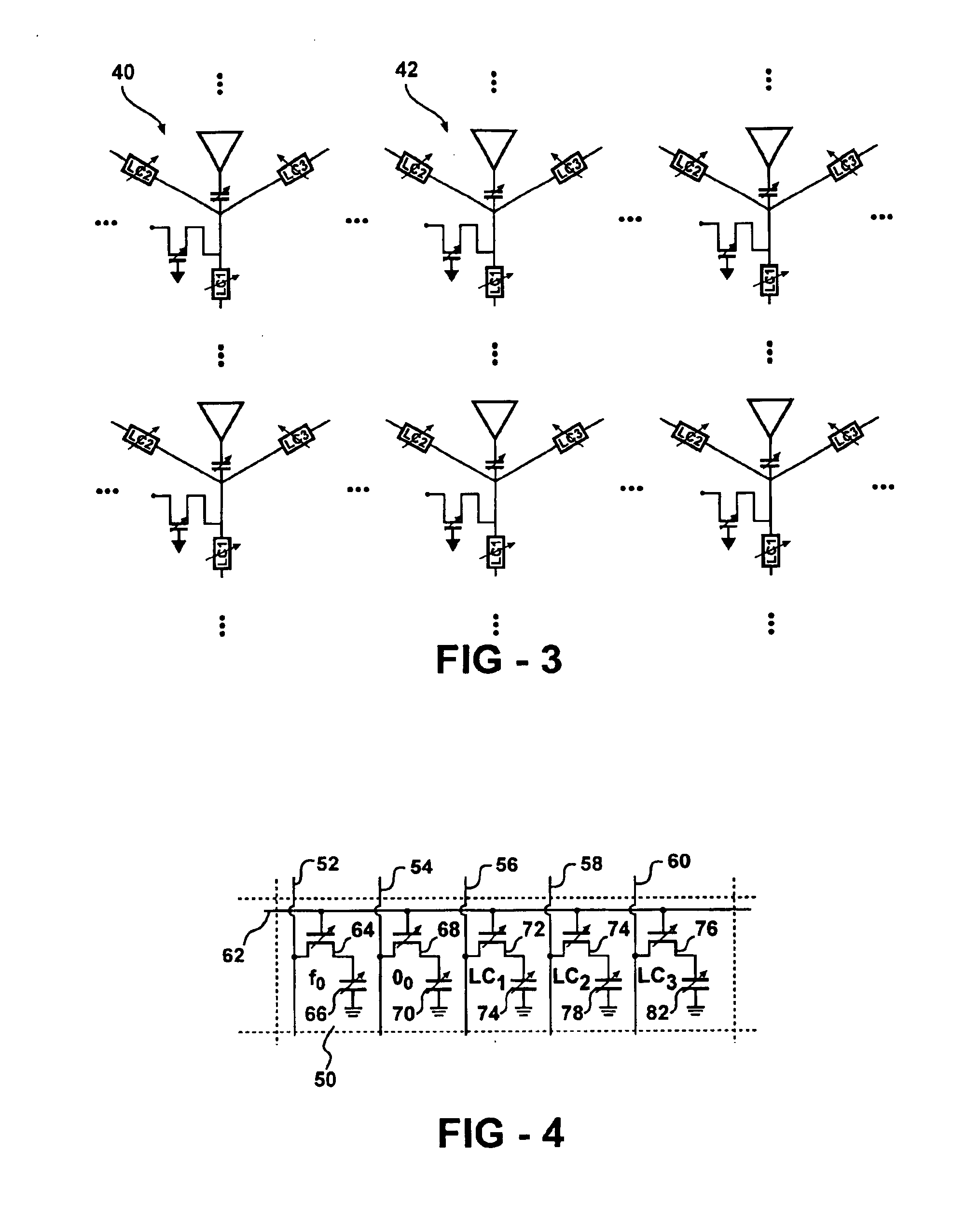
[0018]FIG. 2 shows an antenna pixel including radiative element 20, and five tunable elements, namely frequency control capacitor 22, first interconnection capacitor 24, second interconnection capacitor 26, third interconnection capacitor 28, and phase co...


PUM


Abstract

Passive or active pixelized antenna structures are described in which the radio-frequency (RF) tuning of individual antenna pixel elements, the connections of individual antenna pixel elements to other antenna elements, and optionally the local phase of individual elements or groups of elements, is varied and controlled using tunable elements. Efficient and low-cost control of a large number of tunable elements is provided by matrix addressing techniques.

Description

REFERENCE TO RELATED APPLICATION[0001]This application claims priority of U.S. Provisional Application Ser. No. 60 / 426,993, filed Nov. 14, 2002, the entire content of which is incorporated herein by reference.FIELD OF THE INVENTION[0002]The present invention relates to antennas, in particular to reconfigurable antenna arrays having tunable reactive elements.BACKGROUND OF THE INVENTION[0003]Pixelized, reconfigurable antennas are of interest for many applications. Phased array systems, for example, form one class of such antenna systems, but much simpler antennas are also of interest. Phased array systems are often active antennas, that is, they incorporate active elements such as electrically tunable elements. However, control of such active elements conventionally involves a high degree of complexity.[0004]Pixelized antennas using interconnection switches rely on the availability of switches with appropriate characteristics. For low-cost, light-weight, and thin antennas, and particu...

Claims


Application Information

Patent Timeline
IPC IPC(8): H01Q21/00H01Q3/40H01Q21/06
CPCH01Q3/40H01Q21/061H01Q21/00
Inventor JACKSON, THOMAS N.
Owner PENN STATE RES FOUND
Learn More