Wireless communications antenna assembly generating minimal back lobe radio frequency (RF) patterns

a technology of antenna assembly and back lobe, which is applied in the direction of antenna details, antennas, electrical equipment, etc., can solve the problems of degrading the performance of another antenna located nearby, conventional antenna assemblies, etc., and achieves the effects of minimizing reducing installation costs, and reducing the influence of signal to and from the antenna assembly

Inactive Publication Date: 2005-04-26
LG ELECTRONICS INC +1
View PDF8 Cites 65 Cited by
  • Summary
  • Abstract
  • Description
  • Claims
  • Application Information

AI Technical Summary

Benefits of technology

[0025]However, placing the antennas (e.g., donor and coverage) far apart within a wireless communications system is inappropriate for relatively small areas, such as in a downtown city environment. Also, placing an obstruction or barrier between the antennas increases installation costs and causes cumbersome set up procedures.
[0026]Thus, to address at least the above-identified conventional problems, the present inventors employ a particular antenna assembly structure that effectively minimizes signal influence (e.g., loop formation phenomena and the positive feedback of signals) in a wireless communications system. Namely, signal influence to and from an antenna assembly is minimized by providing a particular antenna assembly structure having at least one attenuating structural element (e.g., an attenuating member, plate, bent panel, wing, etc.) placed behind a reflecting member (reflector) using a non-conductive material for the antenna support structure, wrapping a conductive (e.g., metallic) mesh on a power cable of the feed network (feeder), or any combination of the above.

Problems solved by technology

In particular, conventional antenna assemblies (of for example, a repeater) are problematic in that certain elements therein undesirably influence the function of the other elements that comprise an antenna system.
In other words, the feedback (or positive feedback) of a signal from one antenna degrades the performance of another antenna located nearby.
In particular, the conventional antenna assembly causes relatively large back lobe RF patterns at the backside of the antenna assembly, which are especially problematic in antenna performance.

Method used


Image

  • Wireless communications antenna assembly generating minimal back lobe radio frequency (RF) patterns
  • Wireless communications antenna assembly generating minimal back lobe radio frequency (RF) patterns
  • Wireless communications antenna assembly generating minimal back lobe radio frequency (RF) patterns

Examples


Embodiment Construction

[0035]The present invention provides a wireless communications system involving transmission of signals from a network to a user via an air interface. For example, the wireless communications system may be a mobile communications system, where the network is a communications network and the user is a mobile station.

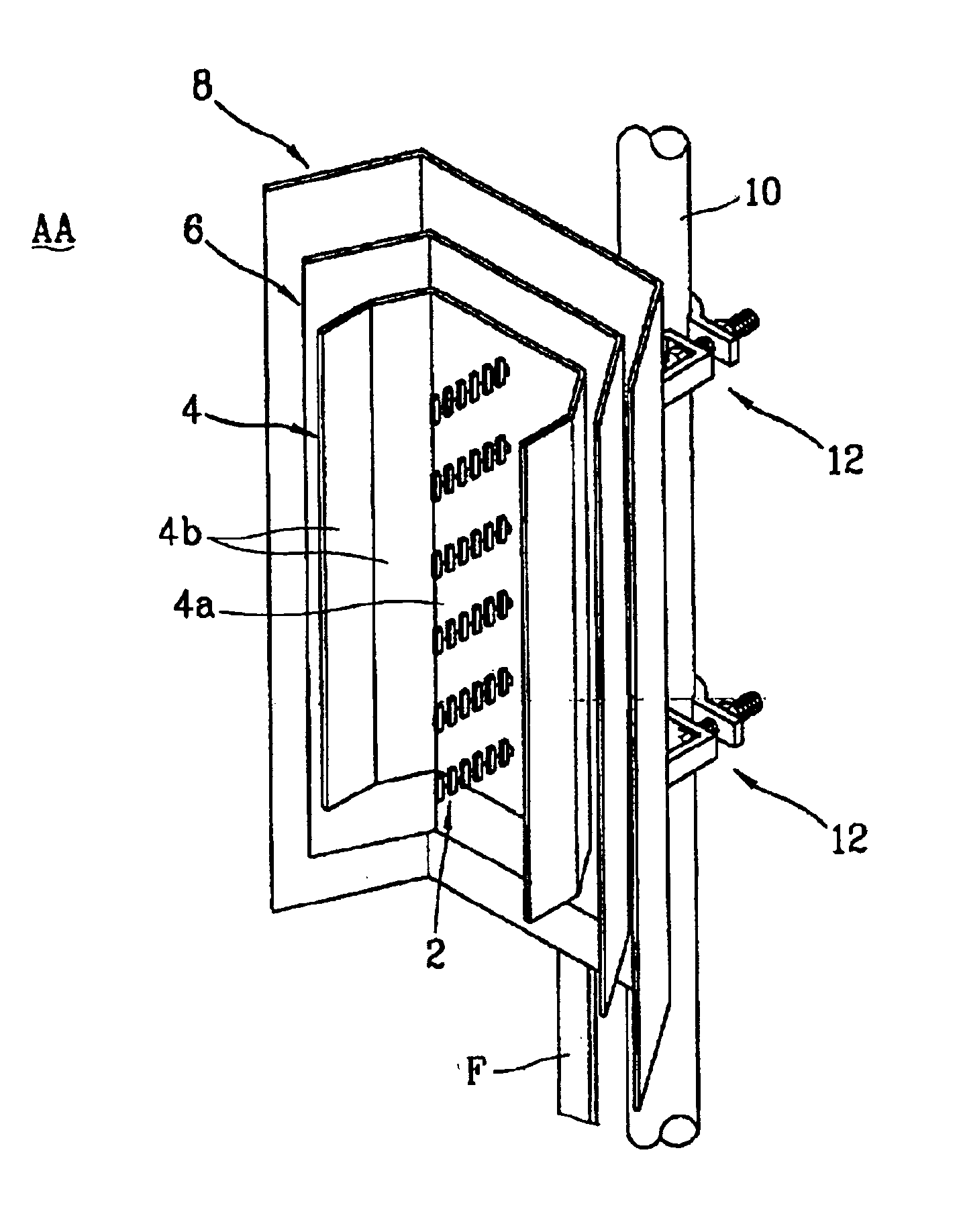
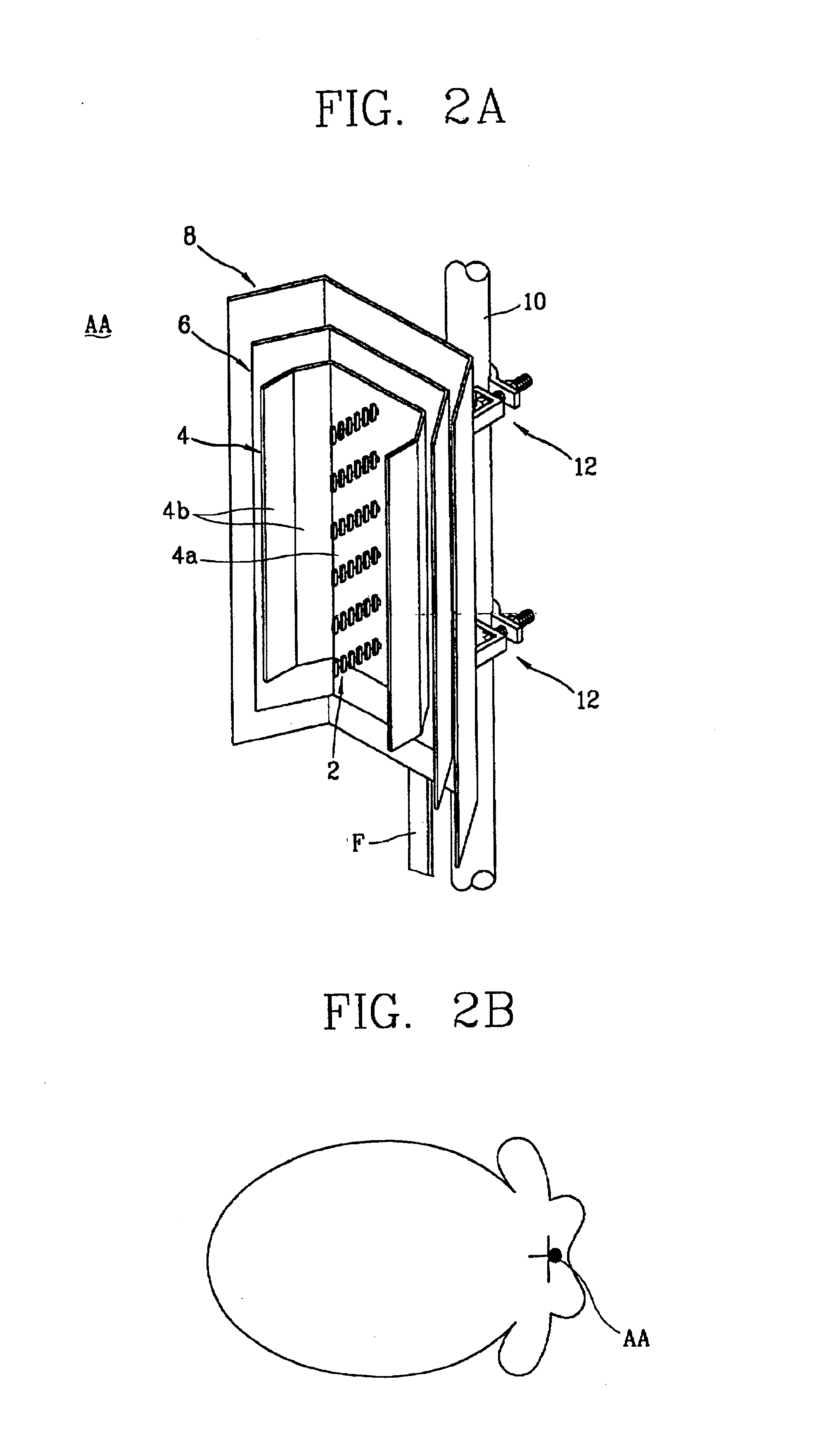
[0036]The present invention provides an improved antenna assembly structure that minimizes signal influence between antennas by reducing the RF pattern back lobes created by the antennas. Here, it should be noted that transmitted signals exhibit several types of signal characteristics, such as direct field, reflection, diffraction, scattering, and the like. Of these characteristics, signal diffraction and scattering mainly contribute to the formation of undesirable back lobes. As such, the present inventors have found that minimizing signal diffraction and scattering effectively reduces signal influence between antennas, e.g., loop formation phenomena caused by (positive)...


PUM


Abstract

An antenna assembly for wireless communications has various components to minimize signal influence when transmitting signals to minimize undesirable loop formation phenomena caused by (positive) feedback of signals. Signal wave scattering and diffraction causing back lobe radio frequency (RF) patterns are minimized by a particular antenna assembly structure having a reflector and at least one attenuating structural member, a metallic mesh wrapping the power cable of a feeder, a non-conductive antenna support structure, or any combination thereof. The dimensions of the various components, in particular the reflector and attenuators, can be varied according to desired wireless communications environment.

Description

CROSS REFERENCE TO RELATED ART[0001]This application claims the benefit of Korean Patent Application No. 2001-71506, filed on Nov. 16, 2001, the contents of which is hereby incorporated by reference in its entirety.TECHNICAL FIELD[0002]The present invention generally relates to wireless communications, and in particular, to a wireless communications system employing a particular antenna assembly structure that generates minimal back lobe radio frequency (RF) patterns.BACKGROUND ART[0003]Wireless communications involving the transmission and reception of data packets and other types of information via wireless, cellular and / or mobile techniques provide the backbone of our information society with widespread business and non-business applications. Hereinafter, such techniques will be simply referred to as “mobile communications” merely for the sake of brevity.[0004]In a typical mobile communications system, a plurality of mobile stations (e.g., cellular / mobile phones, laptop computers...

Claims


Application Information

Patent Timeline
Patent Type & Authority Patents(United States)
IPC IPC(8): H01Q19/02H01Q19/00H01Q1/24H01Q19/10H01Q1/12H01Q21/08
CPCH01Q1/246H01Q21/08H01Q19/10H01Q19/021H01Q19/00
Inventor LEE, HYO-JINKIM, MYUNG-DUK
Owner LG ELECTRONICS INC
Why Eureka
Try Eureka