System and method for resetting a reaction mass assembly of a stage assembly

a technology of reaction mass and stage assembly, which is applied in the field of stage assembly, can solve the problems of reducing the accuracy of positioning the wafer, degrading the accuracy of the exposure apparatus, and the alignment error between the reticle and the wafer, so as to achieve the effect of precise exposure without increasing the size of the exposure apparatus

Inactive Publication Date: 2005-04-26
NIKON CORP
View PDF35 Cites 58 Cited by
  • Summary
  • Abstract
  • Description
  • Claims
  • Application Information

AI Technical Summary

Benefits of technology

[0015]The present invention is directed to a method and apparatus for resetting a reaction mass assembly of a stage assembly. The stage assembly is useful with an apparatus to sequentially position a device for one or more manufacturing operations performed by the apparatus. The stage assembly includes a stage, a stage mover assembly, a reaction mass assembly, a reaction mover assembly and a control system. The stage retains the device. The stage mover assembly moves the stage relative to a stage base. The reaction mass assembly reduces and minimizes the amount of reaction forces from the stage mover assembly that are transferred to the stage base.
[0016]The reaction mover assembly moves the reaction mass assembly relative to the stage base to reset the position of the reaction mass assembly. More specifically, the control system directs and controls current to the reaction mover assembly (i) to control the position of the reaction mass assembly, (ii) to prevent the reaction mass assembly from achieving a constant velocity, (iii) to correct external disturbances that can influence the position of the reaction mass assembly, and (iv) to prevent the center of gravity of the stage assembly from shifting.
[0017]Preferably, the control system controls current to the reaction mover assembly based upon the status of the one or more operations performed by the apparatus. This allows the control system to control and direct current to the reaction mover assembly in a way that minimizes the disturbances created by the reaction mover assembly on the stage assembly and the apparatus. More specifically, the timing and / or the amount of current from the control system directed to the reaction mover assembly is varied to minimize the influence of the disturbances created by the reaction mover assembly on the stage assembly. The timing and / or amount of current can also be varied according the type of operations performed by the apparatus.
[0022]For an exposure apparatus, the control system can control and direct current to the reaction mover assembly at a different rate during an exposure than between exposures. For example, during an exposure, the control system directs current to the reaction mover assembly so that the forces generated by the reaction mover assembly are relatively small and the gain is low. Alternately, between exposures, the control system directs current to the reaction mover assembly so that the forces generated by the reaction mover assembly are relatively large and the gain is high.
[0023]As provided herein, the control system can direct a relatively large current to the reaction mover assembly (i) between the forming of each image on the device, e.g. each chip on a semiconductor wafer, (ii) between the forming of each row of images on the device, e.g. each row of chips on the wafer, (iii) between every scan of the device, or (iv) between each device or wafer processed by the exposure apparatus. With this design, the reaction mover assembly makes relatively large adjustments to the position of the reaction mass assembly when the illumination source is in the off position and makes relatively small adjustments to the position of the reaction mass assembly when the illumination source is in the on position. Thus, the control system directs more current to the reaction mover assembly when the illumination source is in the off position than when the illumination source is in the on position.

Problems solved by technology

Unfortunately, the wafer stage mover assembly generates reaction forces that can vibrate the wafer stage base and the apparatus frame.
As a result thereof, the vibration can cause an alignment error between the reticle and the wafer.
This reduces the accuracy of positioning of the wafer relative to the reticle and degrades the accuracy of the exposure apparatus.
Such vibration resulting from the reaction force deteriorates exposure accuracy of a scanning stepper that performs an exposure operation while scanning a stage (and a wafer or a reticle).

Method used


Image

  • System and method for resetting a reaction mass assembly of a stage assembly
  • System and method for resetting a reaction mass assembly of a stage assembly
  • System and method for resetting a reaction mass assembly of a stage assembly

Examples


second embodiment

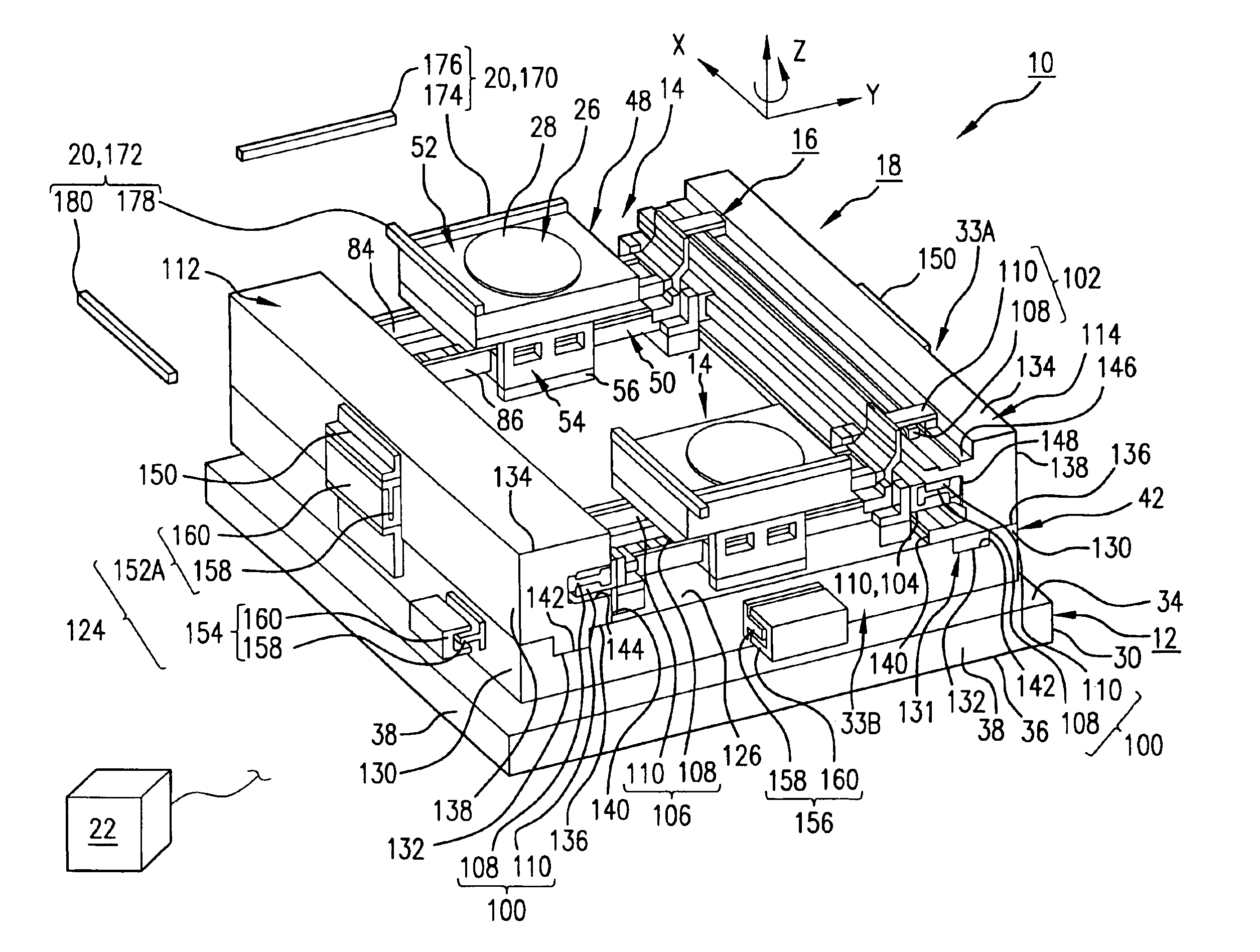
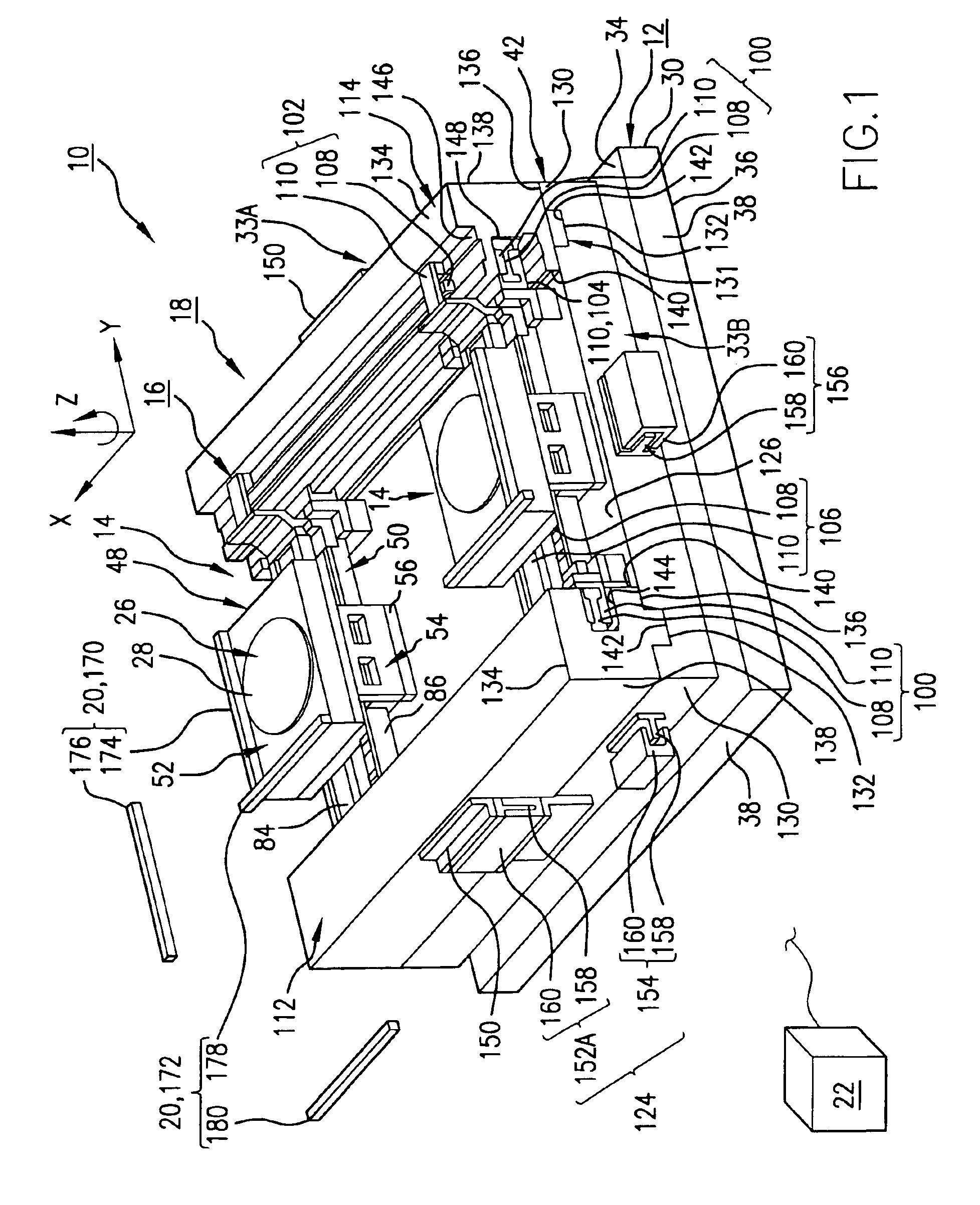
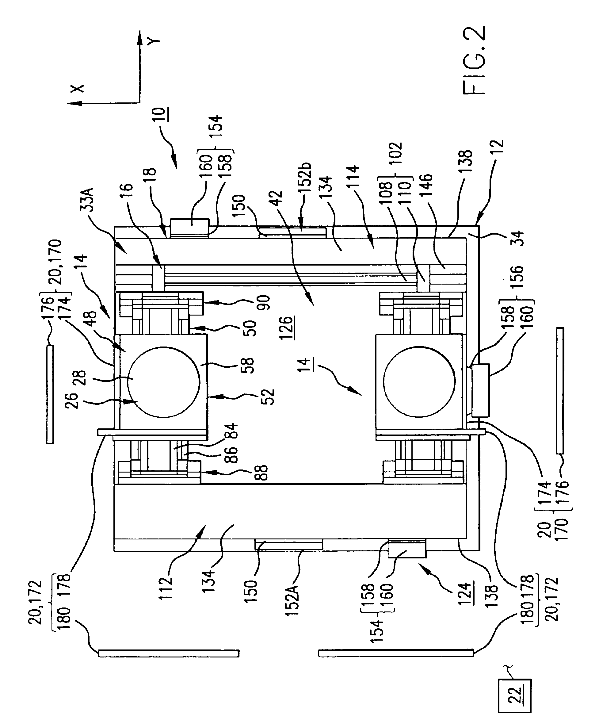
[0180]FIGS. 8-10 illustrate a second embodiment having features of the present invention. In particular, FIG. 8 illustrates a perspective view of the stage assembly 10, FIG. 9 illustrates a top plan view of the stage assembly 10 of FIG. 8, and FIG. 10 illustrates an exploded perspective view of the reaction mass assembly 18. The stage assembly 10 illustrated in FIGS. 8 and 9 includes the stage base 12, a pair of stages 14, the stage mover assembly 16, the reaction mass assembly 18, the measurement system 20, and the control system 22.

[0181]In the embodiment illustrated in FIGS. 8-9, each stage 14, the stage mover assembly 16, the measurement system 20, and the control system 22 are somewhat similar to the equivalent components described above. However, in the embodiment illustrated in FIGS. 8-10, the stage base 12 and the reaction mass assembly 18 differ from the embodiment illustrated in FIGS. 1-3.

[0182]In the embodiment illustrated in FIGS. 8-10, the X reaction component 33A inclu...

third embodiment

[0200]FIGS. 11-13 illustrate a third embodiment having features of the present invention. In particular, FIG. 11 illustrates a perspective view of the stage assembly 10, FIG. 12 illustrates a perspective view of the reaction mass assembly 18, and FIG. 13 illustrates an exploded perspective view of the reaction mass assembly 18. The stage assembly 10 illustrated in FIG. 11 includes the stage base 12, a pair of stages 14, the stage mover assembly 16, the reaction mass assembly 18, and the control system 22. The measurement system is not illustrated in FIG. 11.

[0201]In the embodiment illustrated in FIG. 11, each stage 14, the stage mover assembly 16, and the control system 22 are somewhat similar to the equivalent components described above. However, in the embodiment illustrated in FIGS. 11-13, the stage base 12 and the reaction mass assembly 18 differ from the embodiment illustrated in FIGS. 1-3 and the embodiment illustrated in FIGS. 8-10.

[0202]In the embodiment illustrated in FIGS....

fourth embodiment

[0221]FIGS. 14-16 illustrate a fourth embodiment having features of the present invention. In particular, FIG. 14 illustrates a perspective view of the stage assembly 10, FIG. 15 illustrates a perspective view of the reaction mass assembly 18, and FIG. 16 illustrates an exploded perspective view of the reaction mass assembly 18. The stage assembly 10 illustrated in FIG. 14 includes the stage base 12, a pair of stages 14, the stage mover assembly 16, the reaction mass assembly 18, and the control system 22. The measurement system is not illustrated in FIG. 14.

[0222]In the embodiment illustrated in FIG. 14, each stage 14, the stage mover assembly 16, and the control system 22 are somewhat similar to the equivalent components described above. Further, the stage base 12 and the reaction mass assembly 18 illustrated in FIGS. 14-16 are similar to the stage base 12 and reaction mass assembly 18 illustrated in FIGS. 11-13 and described above. However, in the embodiment illustrated in FIGS. ...


PUM

PropertyMeasurementUnit
of wavelengthaaaaaaaaaa
wavelengthaaaaaaaaaa

Abstract

A stage assembly includes a stage base, a stage, a stage mover assembly, a reaction mass assembly, a reaction mover assembly, and a control system. The stage mover assembly moves the stage relative to the stage base. The reaction mass assembly reduces the reaction forces created by the stage mover assembly that are transferred to the stage base. The reaction mover assembly adjusts the position of the reaction mass assembly relative to the stage base. The control system controls and directs current to the reaction mover assembly in a way that minimizes the influence of disturbances created by the reaction mover assembly on the stage assembly. The timing and / or the amount of current from the control system directed to the reaction mover assembly is varied to minimize the influence of the disturbances created by the reaction mover assembly on the stage assembly.

Description

[0001]This application is a continuation-in-part of U.S. patent application Ser. No. 09 / 714,598, filed Nov. 16, 2000, now abandoned, and of U.S. patent application Ser. No. 09 / 739,772, filed Dec. 20, 2000, now abandoned, the entire disclosures of which are incorporated herein by reference.CROSS REFERENCE TO RELATED APPLICATIONS[0002]As far as permitted, the disclosures of (i) U.S. patent application Ser. No. 09 / 714,747, entitled, “STAGE ASSEMBLY INCLUDING A REACTION MASS ASSEMBLY,” filed on the same day as the present Application, (ii) U.S. patent application Ser. No. 10 / 442,537, entitled “STAGE ASSEMBLY INCLUDING A REACTION ASSEMBLY,” filed on the same day as the present Application, and (iii) U.S. patent application Ser. No. 10 / 453,270, entitled “STAGE ASSEMBLY INCLUDING A REACTION ASSEMBLY THAT IS CONNECTED BY ACTUATORS,” filed on the same day as the present Application, are incorporated herein by reference.BACKGROUND OF THE INVENTION[0003]1. Field of Invention[0004]The present i...

Claims


Application Information

Patent Timeline
Patent Type & Authority Patents(United States)
IPC IPC(8): G03B27/62G03F7/20
CPCG03B27/62G03F7/707G03F7/709G03F7/70766G03F7/70708
Inventor TANAKA, KEIICHIBINNARD, MIKEHAZELTON, ANDREW J.
Owner NIKON CORP
Why Eureka
Try Eureka