

Method for detecting a human face and an apparatus of the same
a detection method and technology of a human face, applied in the field of detection methods of human faces and an apparatus of the same, can solve the problems of inability to separate mustache and mouth, lot of incorrect detection, etc., and achieve the effect of small calculation amount and high accuracy
- Summary
- Abstract
- Description
- Claims
- Application Information
AI Technical Summary
Benefits of technology
Problems solved by technology
Method used
Image

Examples
first embodiment
[0045](First Embodiment)
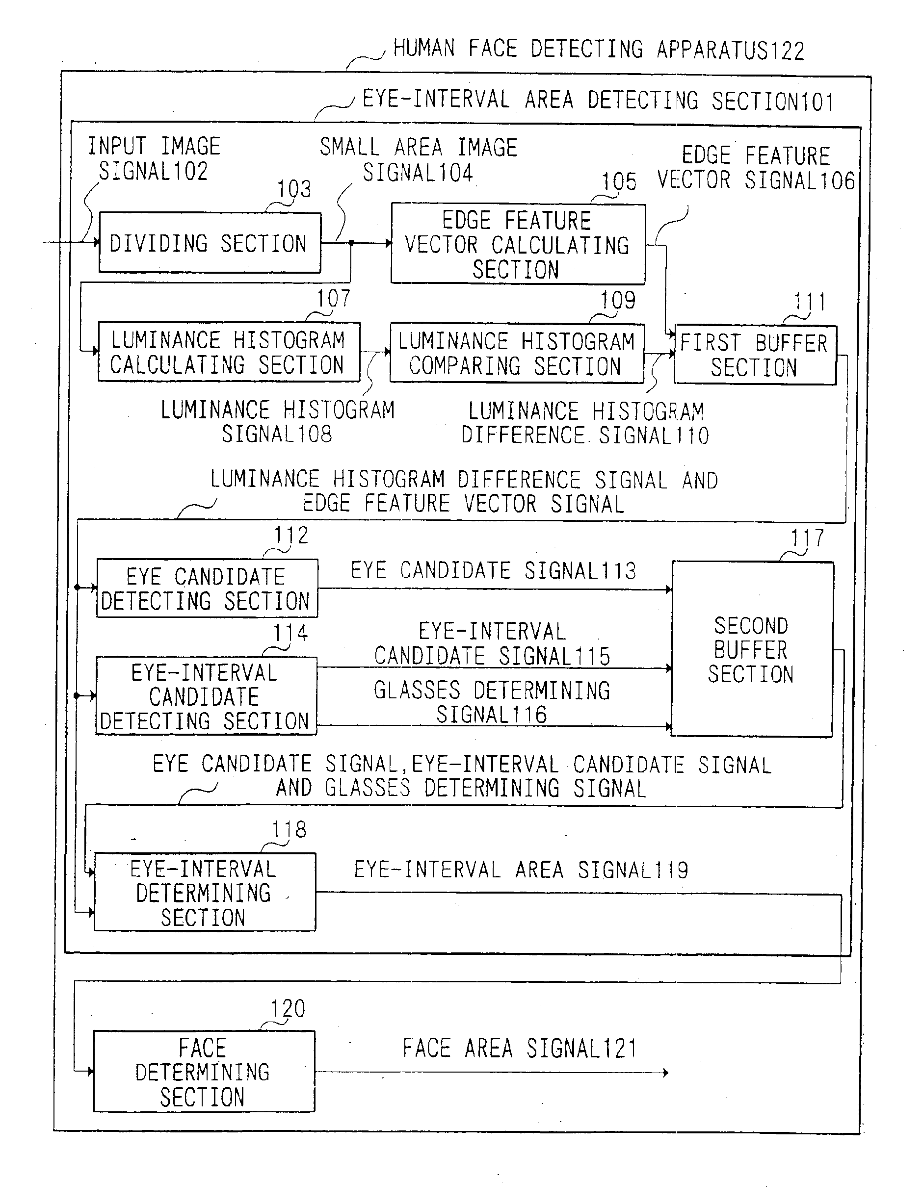
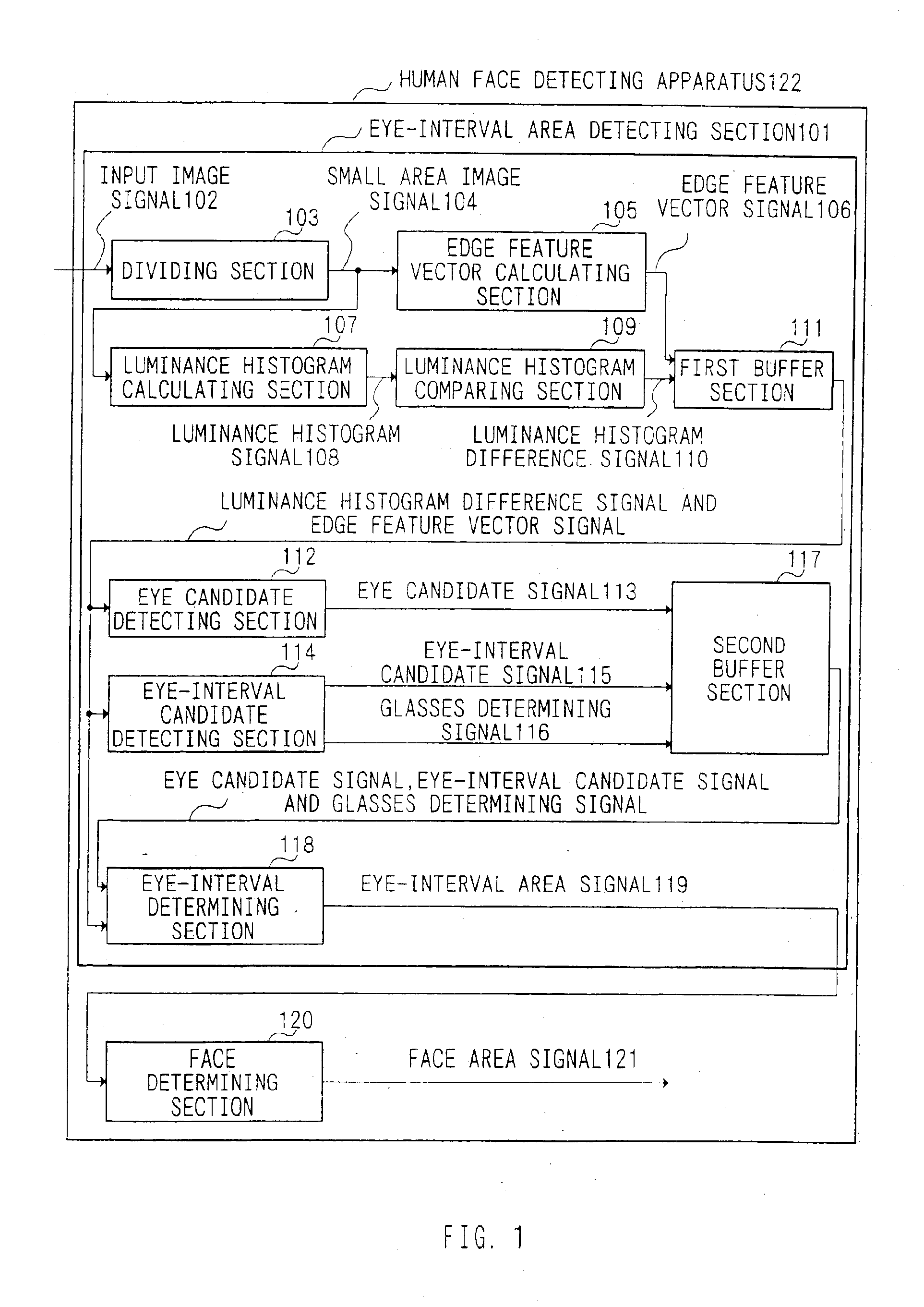
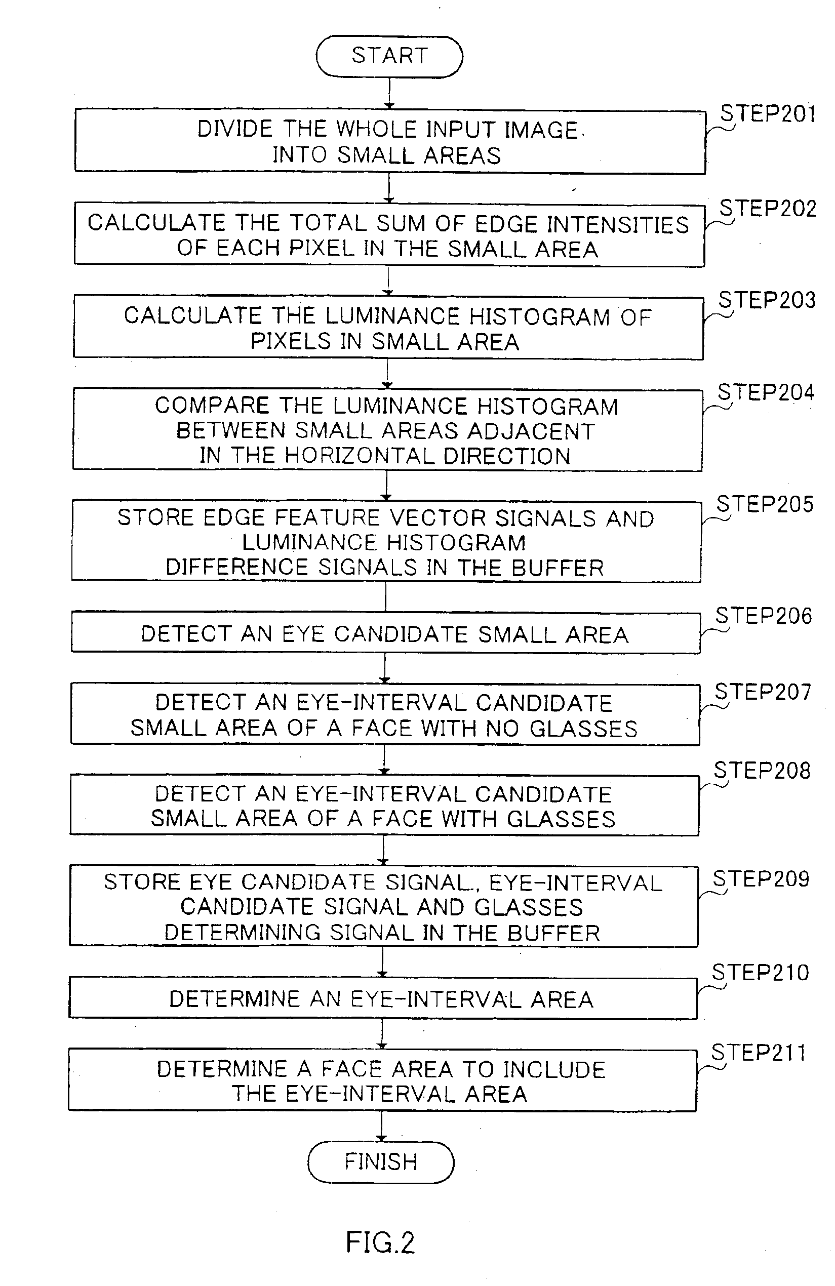
[0046]FIG. 1 is a diagram illustrating a schematic configuration of an apparatus for detecting a human face in the first embodiment of the present invention. In FIG. 1, an input image signal 102 input to human face detecting apparatus 122 is input to dividing section 103 of eye-interval area detecting section 101. Hereinafter, an interval between eyes is also referred to as an eye-interval.
[0047]Dividing section 103 divides the whole image of the input image signal 102 into a plurality of small areas, and sequentially outputs an image of each small area as a small area image signal 104.
[0048]Edge feature vector calculating section 105 reads the small area image signal 104, and outputs a sum total of edge intensities of each pixel in the small area as an edge feature vector signal 106.
[0049]Luminance histogram calculating section 107 reads the small area image signal 104, and outputs the histogram of pixels in the small area as a luminance histogram signal 108...
second embodiment
[0086](Second Embodiment)
[0087]The second embodiment provides a more accurate apparatus for detecting a human face by combining two eye-interval area detecting sections 101 explained in the first embodiment.
[0088]FIG. 4 is a diagram illustrating a schematic configuration of the apparatus for detecting a human face in the second embodiment of the present invention. In FIG. 4, in human face detecting apparatus 401, an input image signal 402 is input to partial image generating section 403.
[0089]Partial image generating section 403 fetches an image of an area 501 and another image of an area 502 shown in FIG. 5 from the whole image of the input image signal 402, and outputs a first partial image signal 404 and a second partial image signal 405.
[0090]First eye-interval area detecting section 406 reads the first partial image signal 404 to detect an eye-interval area, and outputs coordinates of the eye-interval area as a first eye-interval area candidate signal 407.
[0091]Second eye-inter...
third embodiment
[0111](Third Embodiment)
[0112]The third embodiment provides a more accurate apparatus for detecting a human face by combining the eye-interval area detecting section explained in the first embodiment and a section for examining the vicinity of an eye-interval area.
[0113]FIG. 8 is a diagram illustrating a schematic configuration of the apparatus for detecting a human face in the third embodiment of the present invention. In FIG. 8, an input image signal 802 is input to human face detecting apparatus 821, and is input to eye-interval candidate setting section 803 in eye-interval area detecting section 801.
[0114]Eye-interval candidate setting section 803 reads the input image signal 802, sets an eye-interval candidate area, and outputs coordinates of the eye-interval candidate area as an eye-interval area candidate signal 804.
[0115]Eye candidate setting section 805 reads the eye-interval area candidate signal 804, sets an eye candidate area on each of the right and left sides of the ey...
PUM
 Abstract
Description
Claims
Application Information