Eureka AIR delivers breakthrough ideas for toughest innovation challenges, trusted by R&D personnel around the world.

Double-sided high speed printing apparatus and method

Inactive Publication Date: 2005-05-03
ESCHER GRAD TECH
View PDF12 Cites 1 Cited by
  • Summary
  • Abstract
  • Description
  • Claims
  • Application Information

AI Technical Summary

Benefits of technology

[0006]It is an object of the invention to provide an apparatus and method for conducting a continuous sheet of printable material through a printing apparatus to permit printing on both a first side and a second side of the material for high-speed double-sided printing. The apparatus is compact, eliminates flutter and smudging, and has an arrangement of print heads that fire in one direction.

Problems solved by technology

Such attempts have proved unsatisfactory when incorporated in multiple print head ink-jet printers in which a plurality of ink-jet print heads are aligned along a predefined path of a continuous strip of paper or like printable material.
The paper strip is prone to flutter over the platen because of the extended distance between the guide rollers or the like that is necessary to permit all of the print heads to print on the paper without roller means that lead to smudging of freshly deposited ink.
This fluttering gives rise to unacceptable variations in the spacing between the printable material surface and the print heads.

Method used


Image

  • Double-sided high speed printing apparatus and method
  • Double-sided high speed printing apparatus and method
  • Double-sided high speed printing apparatus and method

Examples


Embodiment Construction

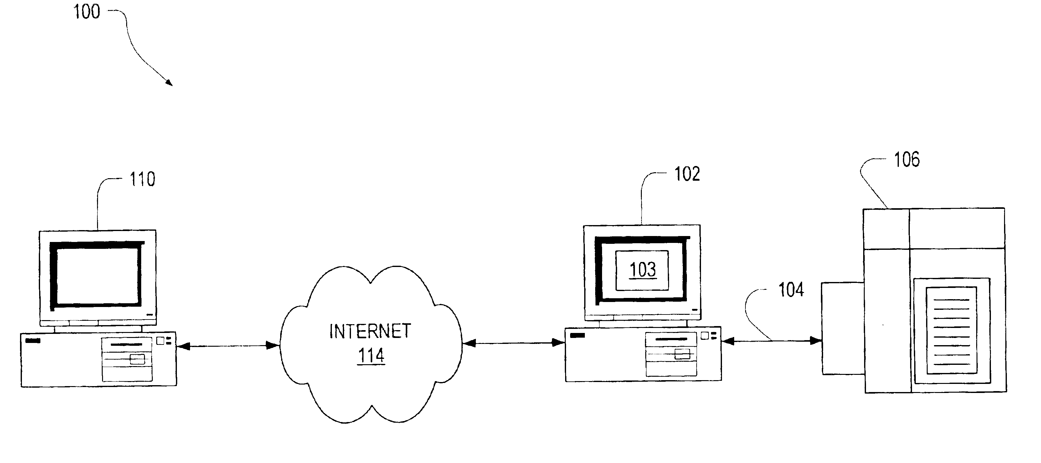
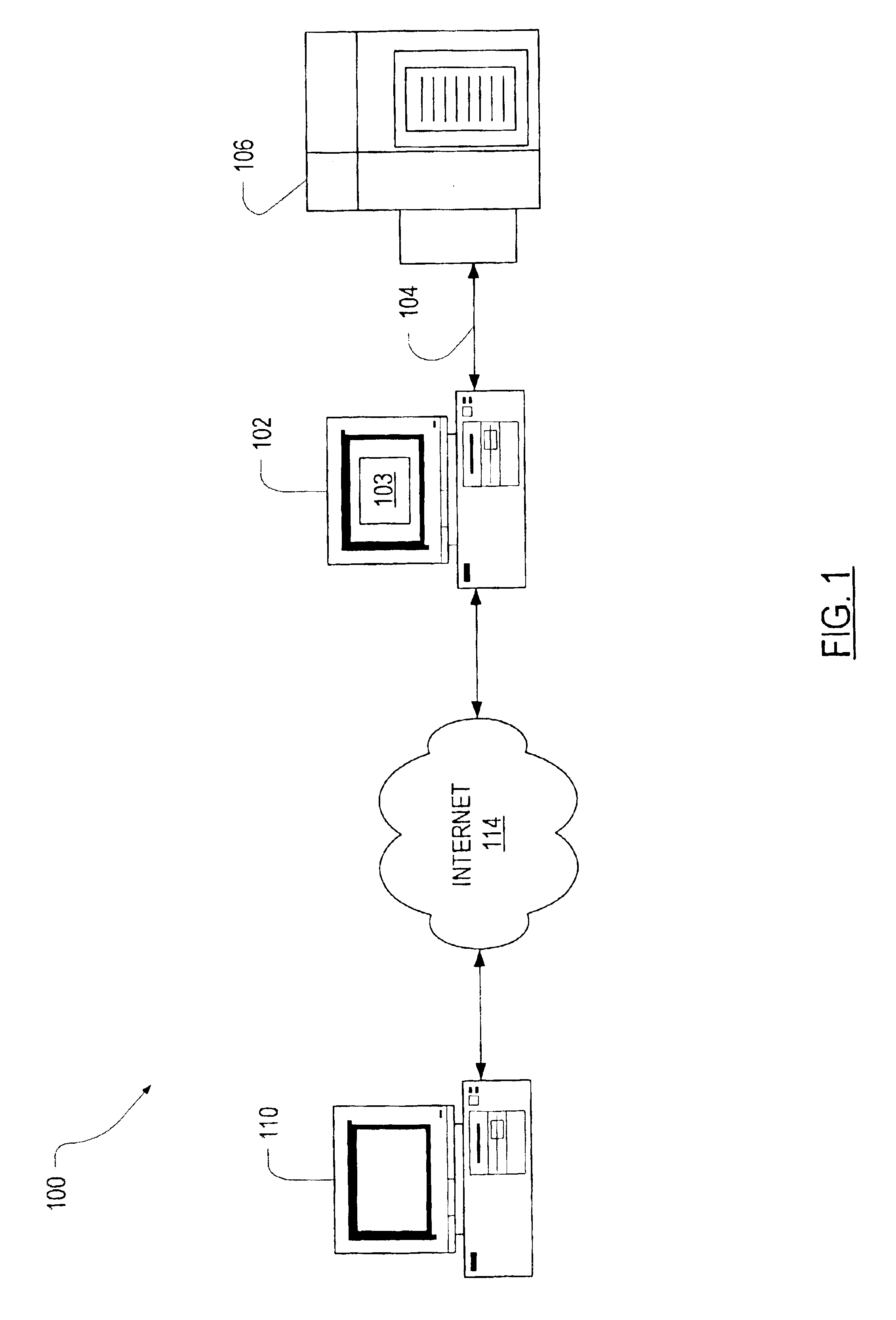
[0018]FIG. 1 is a schematic diagram illustrating an environment 100 in which the invention may be deployed; the environment 100 comprising a computer 102 connected 104 to a printer 106. The connection 104 may be a computer network such as Ethernet; a serial connection such as universal serial bus (USB) or IEEE 1394; a parallel port connection; or a wireless connection such as Bluetooth or IEEE 802.11b. The computer 102 preferably includes a print manager 103. A plurality of remote computers 110 (only one shown for convenience) may also be communicatively coupled to the computer 102 via a packet switching network such as the Internet 114. Images (not shown) 110 may be transferred from the remote computer 110 via the Internet 114 to the print manager 103 in the computer 102, or may originate in the computer 102.

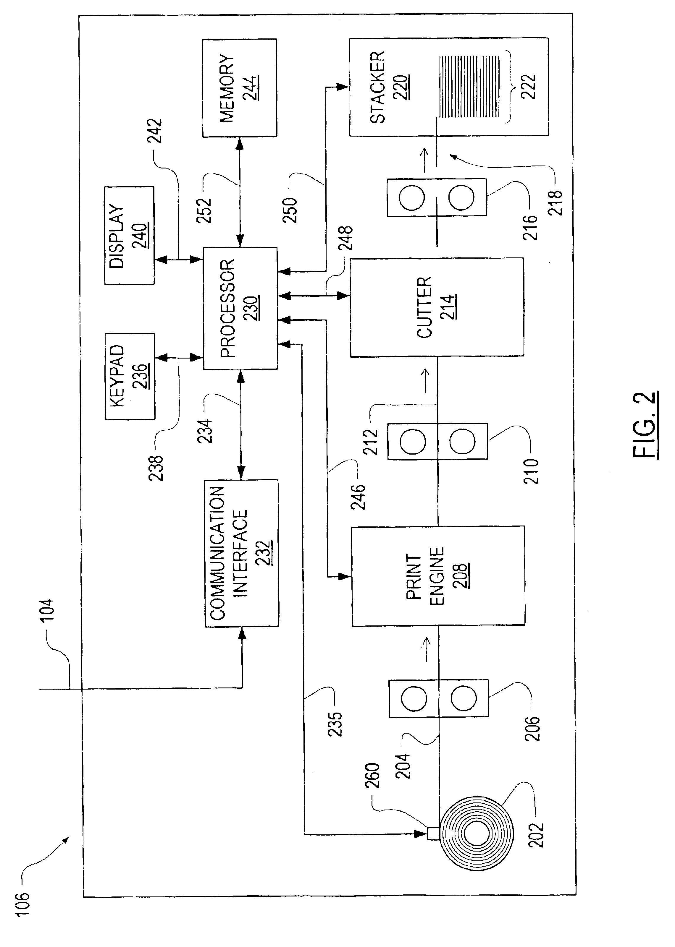
[0019]FIG. 2 is a block diagram of the printing apparatus 106 shown in FIG. 1. The printing apparatus 106 receives a source of printable material 204 which is preferably a web ...


PUM


Abstract

An apparatus for double-sided high-speed printing on a continuous sheet of printable material having a first guide, a second guide, a third guide, and a fourth guide providing a first print area between the first and second guides for printing on a first side of the material and a second print area between the third and fourth guides for printing on a second side of the material. A first plurality of print heads print in the first print area and a second plurality of print heads print in the second print area. The first and second plurality of print heads all fire in a same direction. Bends in the material provided by the guides permit a compact arrangement that eliminates flutter of the material in the print areas.

Description

CROSS-REFERENCE TO RELATED APPLICATIONS[0001]This is the first application filed for the present invention.TECHNICAL FIELD[0002]This invention relates to ink-jet printers and particularly to those having a plurality of ink-jet heads for printing on both sides of a continuous strip of printable material.BACKGROUND OF THE INVENTION[0003]One important requirement for high quality ink-jet printing is that there be an unvarying distance between ink-jet print head nozzles and a print surface of the strip of paper to be printed.[0004]Prior art attempts to provide this constant distance used a fixed, flat platen. Such attempts have proved unsatisfactory when incorporated in multiple print head ink-jet printers in which a plurality of ink-jet print heads are aligned along a predefined path of a continuous strip of paper or like printable material. Consider an elongated flat platen mounted opposite to the series of ink-jet print heads, and with the paper strip fed over the platen by guide rol...

Claims


Application Information

Patent Timeline
IPC IPC(8): B41J13/14B41J3/60
CPCB41J13/14B41J3/60
Inventor KHALID, NAJEEB
Owner ESCHER GRAD TECH
Why Eureka
Eureka Blog
Learn More