Web splicing method and web splicing apparatus

Inactive Publication Date: 2005-05-03
ZUIKO CORP
View PDF13 Cites 7 Cited by
  • Summary
  • Abstract
  • Description
  • Claims
  • Application Information

AI Technical Summary

Benefits of technology

[0008]A change in an amount of the web stored in the accumulator can be determined from a positional change of the movable roller. Specifically, when the first or second driver is moving away from a fixed roller associated with the accumulator, the velocity at which the web is fed out from the first or second respective roll is greater than the velocity at which the web is output from the accumulator (e.g., a line velocity), thereby increasing the amount of the web stored in the accumulator. On the other hand, when the movable roller is moving

Problems solved by technology

While the diameter of the second roll may be obtained by directly measuring

Method used


Image

  • Web splicing method and web splicing apparatus
  • Web splicing method and web splicing apparatus
  • Web splicing method and web splicing apparatus

Examples


Example

[0016]One embodiment of the present invention will now be described with reference to the drawings.

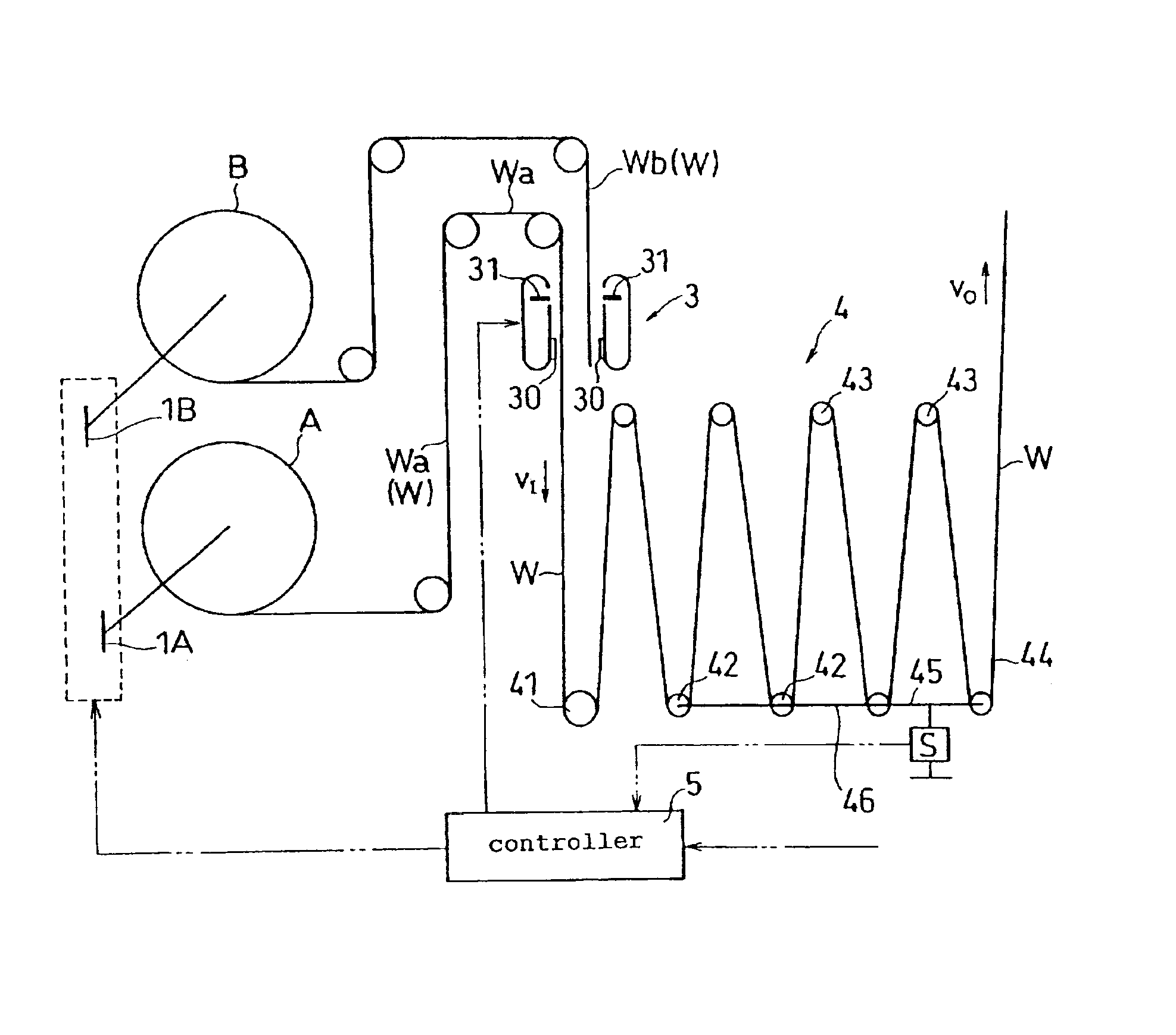
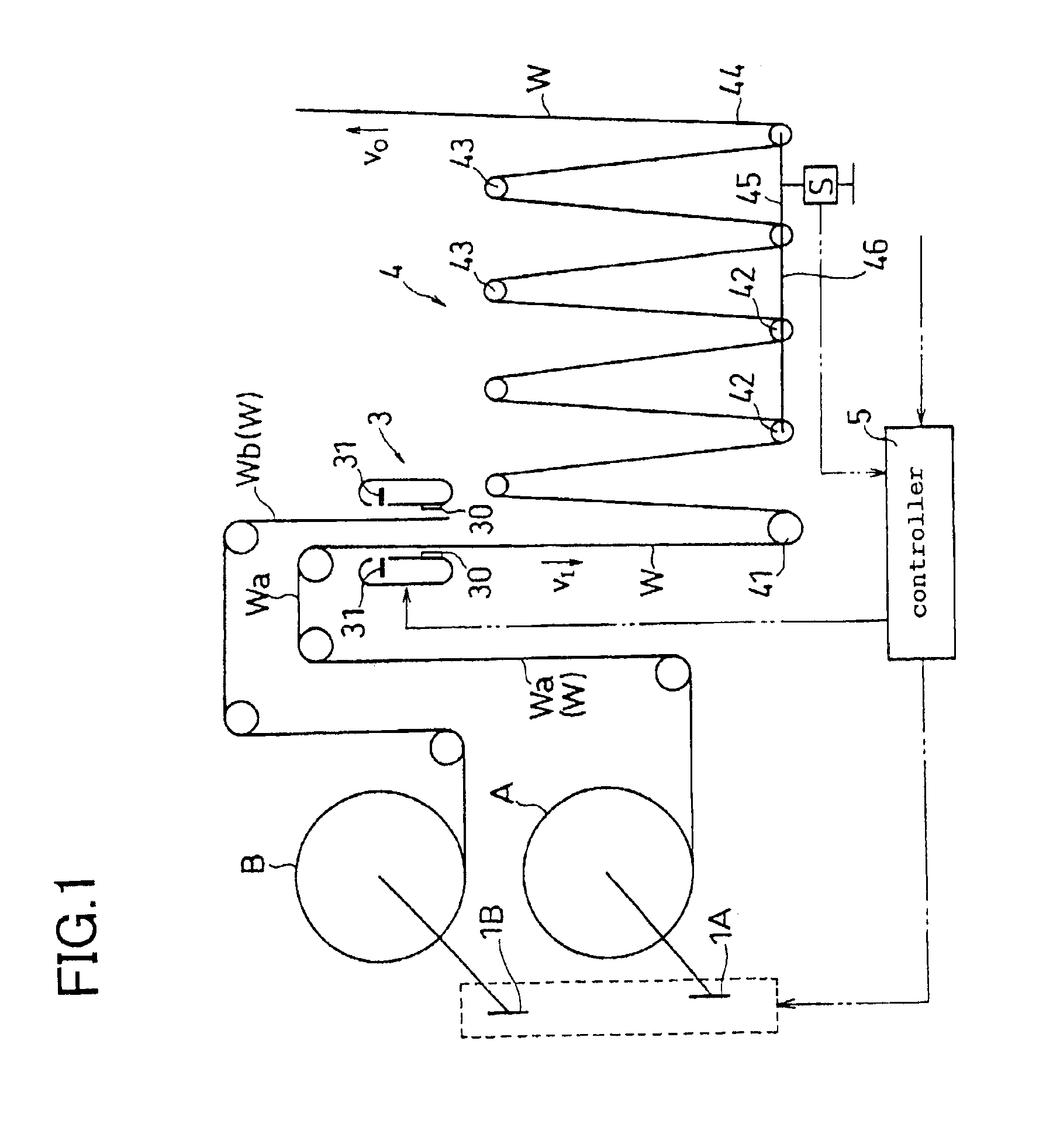
[0017]A splicing apparatus illustrated in FIG. 1 alternately transfers a first web Wa fed from a first roll A and a second web Wb fed from a second roll B while connecting the first web Wa and the second web Wb together. The splicing apparatus includes a first driver 1A for spinning the first roll A, a second driver 1B for spinning the second roll B, a splicer 3, and an accumulator 4.

[0018]The first driver 1A and the second driver 1B may be driven separately by independent motors (not shown), or by a single motor while switching the connection therebetween by a clutch (not shown), or the like. Note that the web W is moving at a velocity VO by a driver (not shown). For example, when the driver is connected to a motor, a predetermined signal may be issued for each turn of the motor, based on which the velocity VO can be known. Such a motor may be a servo motor, or the motor that be vecto...


PUM

PropertyMeasurementUnit
Diameteraaaaaaaaaa
Speedaaaaaaaaaa
Velocityaaaaaaaaaa

Abstract

The present invention provides a web splicing method and a web splicing apparatus with which a line velocity on an output side of the splicing apparatus does not fluctuate through a web splicing operation. The method and apparatus are further operable to maintain a line velocity at a predetermined velocity after the web splicing operation. The method of the present invention includes the steps of: connecting a second web Wb fed out from a second roll B to a first web Wa; cutting off the first web Wa at a position between a point at which the second web Wb is connected to the first web Wa and a first roll A; spinning the second roll B to feed out the second web Wb; obtaining a value of a diameter of the second roll B based on a state of an accumulator 4; and controlling a circumferential velocity of the second roll B based on the obtained diameter.

Description

FIELD OF THE INVENTION[0001]The present invention relates to a web splicing method and a web splicing apparatus.BACKGROUND OF THE INVENTION[0002]Japanese Laid-Open Patent Publication No. 10-45290 discloses an automatic web splicing apparatus for splicing a web with another web while maintaining a constant tension on the web. With the conventional apparatus, the web velocity is detected by a line pulse generator on the output side of the automatic splicing apparatus to calculate the diameter of a roll of web based on the web velocity, or the like, and the braking force is controlled based on the diameter of the roll, or the like, thereby maintaining a constant torque. However, maintaining a constant line velocity on the output side of the automatic splicing apparatus is not taken into consideration.SUMMARY OF THE INVENTION[0003]Thus, it is an object of the present invention to provide a web splicing method and a web splicing apparatus with which the line velocity on an output side of...

Claims


Application Information

Patent Timeline
IPC IPC(8): B65H19/18B65H23/188B65H21/00
CPCB65H19/1852B65H2301/46412B65H2401/1121B65H2401/115B65H2403/72B65H2511/112B65H2511/142B65H2513/10B65H2555/24B65H2301/46327B65H2220/01B65H2220/03B65H2220/02B65H2401/112B65H2401/11B65H2511/14
Inventor HIRATA, TSUGIOOYAGI, YOSHINOBU
Owner ZUIKO CORP
Why Eureka
Try Eureka