Electrical connector with retention clip

a technology of electric connectors and retention clips, which is applied in the direction of coupling contact members, coupling device connections, electrical apparatus construction details, etc., can solve the problems of pins and terminals being liable to sustain damage, electrical connection between the cpu and the pcb being disrupted or even completely failed,

Inactive Publication Date: 2005-05-03
HON HAI PRECISION IND CO LTD
View PDF15 Cites 25 Cited by
  • Summary
  • Abstract
  • Description
  • Claims
  • Application Information

AI Technical Summary

Benefits of technology

[0010]Another object of the present invention is to provide an electrical connector configured so that the operational lever of the connector can accurately be retained in the second position.
[0011]To achieve the above objects, an electrical connector in accordance with a preferred embodiment of the present invention is for connecting a central processing unit (CPU) with a printed circuit board (PCB). The connector comprises an insulative base, a cover mounted on the base, a plurality of terminals received in the base, and an actuator. The base comprises an extending portion extending from an end portion thereof. The extending portion comprises a receiving space with a receiving groove, a receiving recess, and a receiving slot. The extending portion defines a projection protruding from an end thereof with a hook portion inwardly formed from a top of the projection. The actuator actuates the cover to slide along the base, and comprises an operational lever and an axle engaged with the operational lever. A coil spring is attached around the axle. The coil spring comprises a main body received in the receiving groove, a first end, and a second end fastened in the receiving slot. The first end of the coil spring is attached to a cutout of the operational lever and rotates under force form the operational lever. As a result, the operational lever can only be retained in a first position or in a second position. An U-shaped retention clip is locked around the periphery of the projection so that the operational lever of the connector can accurately be retained in the second position.

Problems solved by technology

The pins and the terminals are thus liable to sustain damage.
As a result, the electrical connection between the CPU and the PCB is disrupted or may even fail altogether.

Method used


Image

  • Electrical connector with retention clip
  • Electrical connector with retention clip
  • Electrical connector with retention clip

Examples


Embodiment Construction

[0022]Reference will now be made to the drawings to describe the present invention in detail.

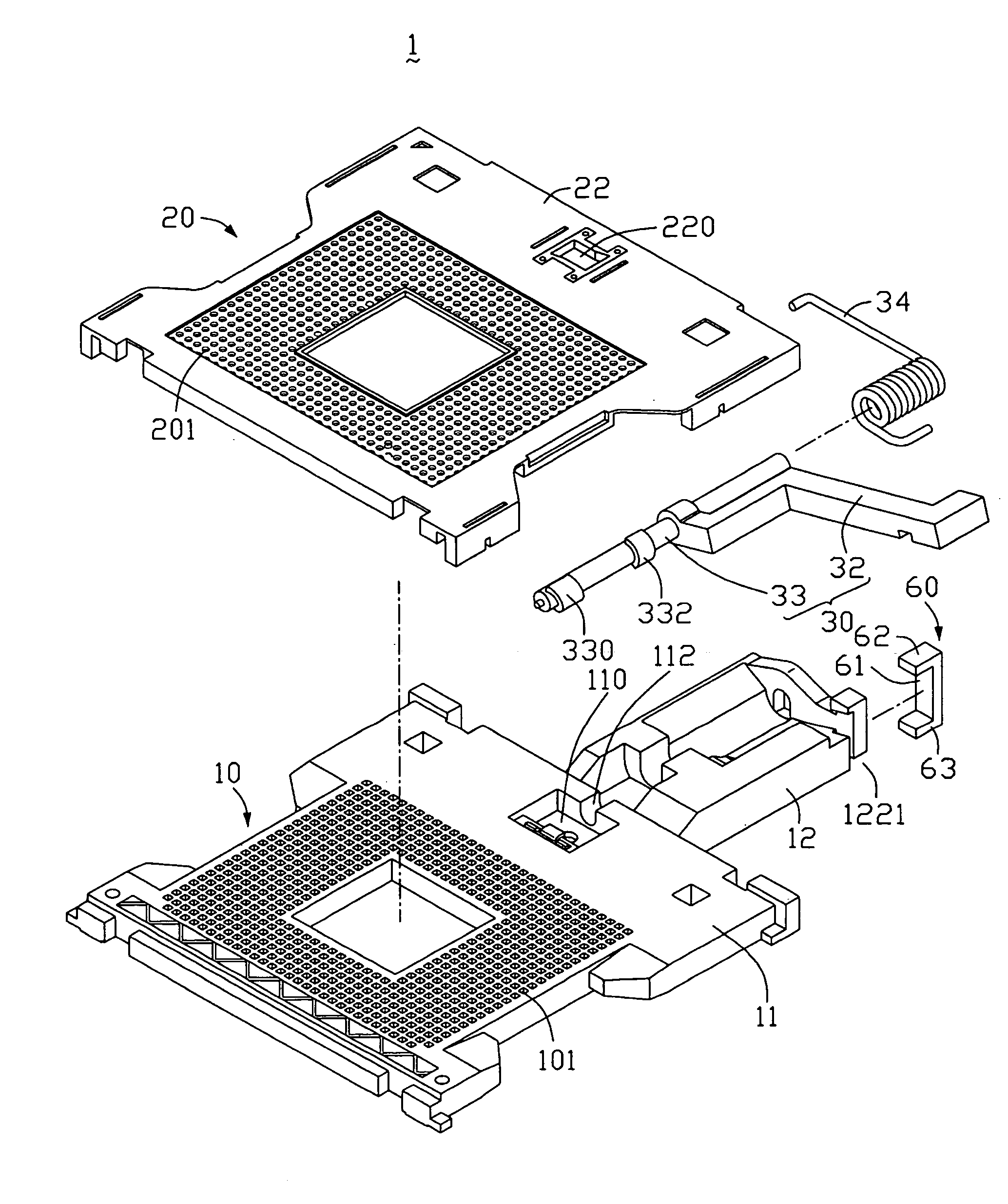
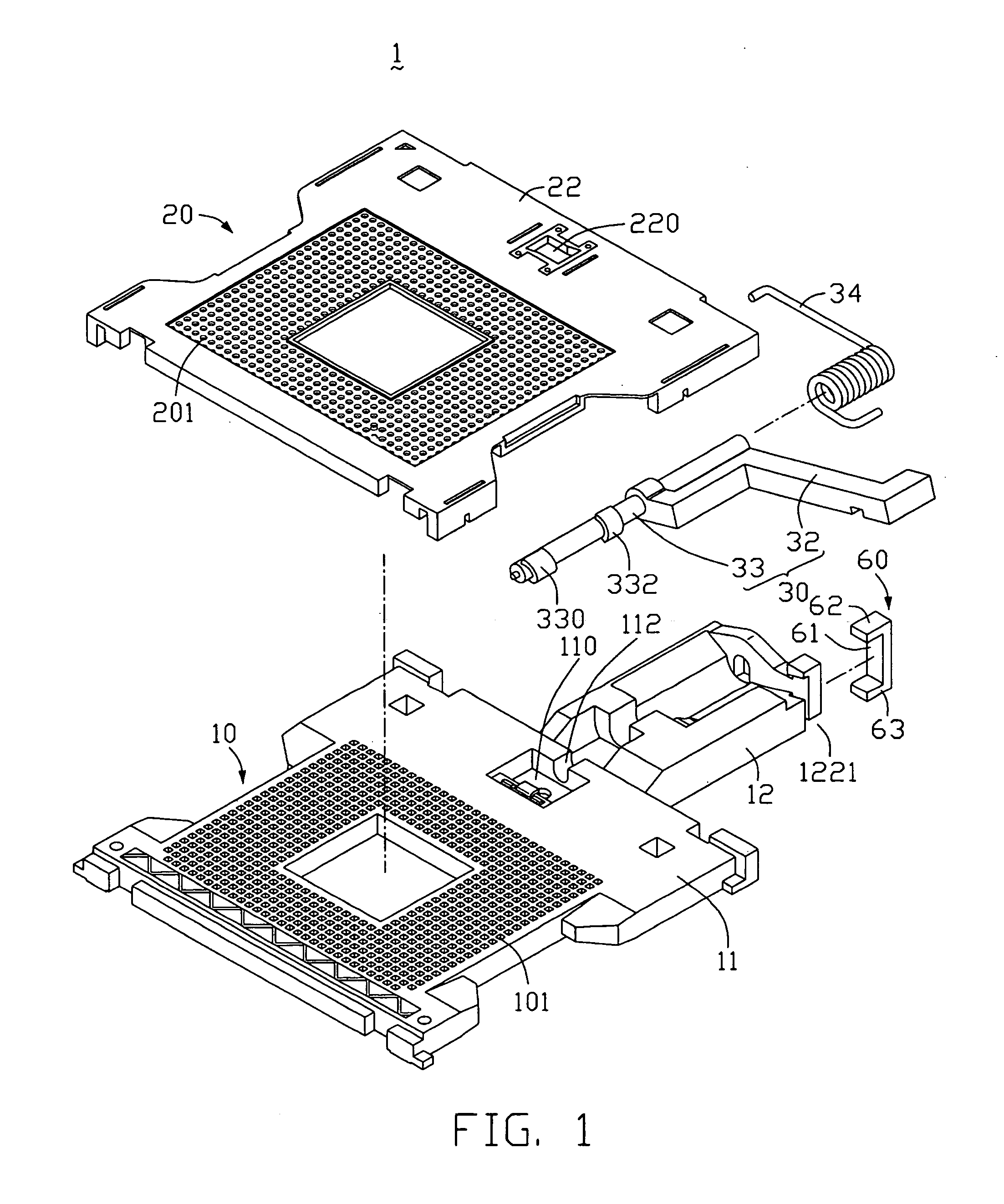
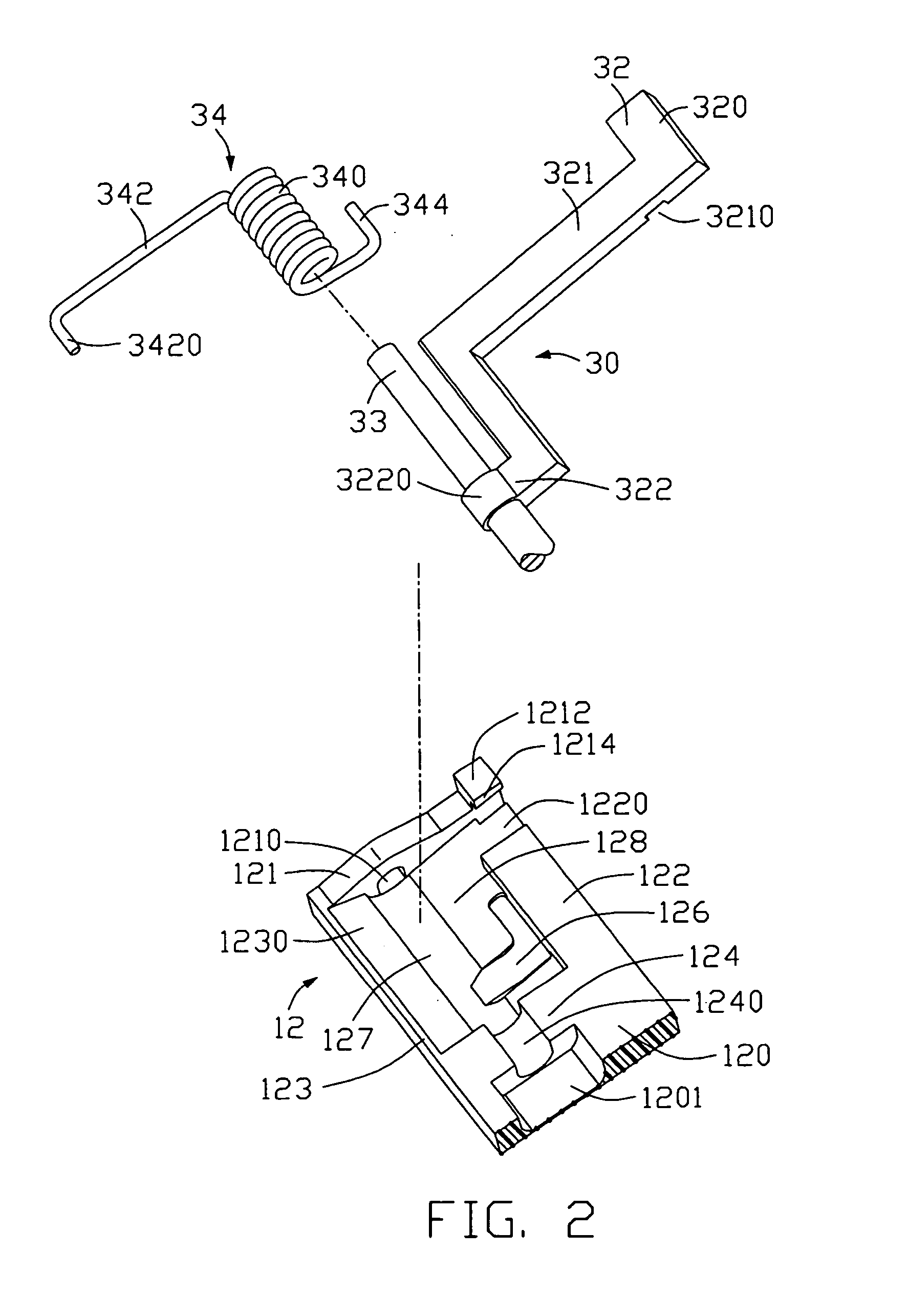
[0023]Referring to FIGS. 1, 2 and 3, an electrical connector 1 in accordance with the preferred embodiment of the present invention is used for electrically connecting an electronic package such as a central processing unit (CPU) (not shown) with a circuit substrate such as a printed circuit board (PCB) (not shown). The electrical connector 1 comprises an insulative base 10 fixed on the PCB, a rectangular cover 20 slidably mounted on the base 10, and an actuator 30 actuating the cover 20 to slide along the base 10.

[0024]The cover 20 comprises a main body (not labeled) and a broad first end portion 22. A rectangular opening (not labeled) is defined in a middle of the main body. A plurality of passages 201 is defined in the main body around the opening, the passages 201 being arranged in a rectangular array. A top hole 220 is defined in a middle of the first end portion 22.

[0025]The base 10 de...


PUM


Abstract

An electrical connector (1) includes a housing (10), a cover (20), and an actuator (30). The base includes an extending portion (12) with a projection (1212) and a hook portion (1214) inwardly formed a top of the projection. The actuator includes an operational lever (32) and an axle (33) engaged with the operational lever. A coil spring (34) is mounted around the axle and defines a first end (342) at a free end thereof. A retention clip (60) is mounted on the projection and includes a base portion (61), a first and second extending walls (62, 63) extending from two opposite ends of the base portion. The coil spring is attached to the operational lever and rotates under force from the operational lever, and the retention clip is tightly fastened on the projection, thereby the operational lever can only be retained in a first position or a second position.

Description

BACKGROUND OF THE INVENTION[0001]1. Field of the Invention[0002]The present invention relates to an electrical connector for electrically connecting a central processing unit (CPU) chip with a printed circuit board (PCB), and particularly to an electrical connector with an operational lever and a retention clip.[0003]2. Description of the Prior Art[0004]CPU sockets are widely used for electrically connecting CPUs with PCBs. A CPU socket usually comprises a base, and a cover slidably engaged on the base. An actuator actuates the cover to slide along the base, such that contact pins of the CPU are pushed to electrically mate with a multiplicity of contacts secured in the base. This kind of electrical connector is disclosed in U.S. Pat. Nos. 6,280,223 and 6,338,639.[0005]FIG. 7 shows a conventional electrical connector 9. The connector 9 comprises a base 90, and an actuator 94 actuating the cover 92 to slide along the base 90. The cover 92 defines a plurality of passages 921 in a recta...

Claims


Application Information

Patent Timeline
Patent Type & Authority Patents(United States)
IPC IPC(8): H05K7/10
CPCH05K7/1007
Inventor LIN, NICKCUI, LINJIANGZHANG, XUE BINYU, WEI
Owner HON HAI PRECISION IND CO LTD
Why Eureka
Try Eureka