Change-speed control system for utility vehicle having stepless change-speed apparatus for speed-changing engine output and transmitting the speed-changed output to traveling unit

a control system and utility vehicle technology, applied in the direction of fluid gearings, machines/engines, gearings, etc., can solve the problem of affecting the start of the vehicl

Inactive Publication Date: 2005-05-03
KUBOTA LTD
View PDF5 Cites 14 Cited by
  • Summary
  • Abstract
  • Description
  • Claims
  • Application Information

AI Technical Summary

Benefits of technology

[0006]In view of the above-described state of the art, a primary object of the invention is to provide a change-speed control system capable of avoiding the above-described trouble at the start or low-speed traveling of the vehicle when the change-speed operations of the engine and the stepless change-speed apparatus are effected in operative connection with each other.
[0009]Therefore, according to this change-speed control system, like the conventional construction, when the engine speed is increased in response to an operation of the accelerator controller, the stepless change-speed apparatus too may be speed-changed to the acceleration side in accordance therewith, thus allowing vehicle travel with easy speed adjustment. And, at the same time, even when a relatively large driving load is applied, the possibility of shortage in the engine output is low, so that the vehicle may be started smoothly.
[0010]The above-described change-speed control linkage device may be an electric or mechanical or electric-mechanical type device. According to one preferred embodiment, the change-speed control linkage device comprises a pivot link mechanism for dividing an operational displacement of the accelerator controller by a predetermined ratio between an operational displacement of the stepless change-speed apparatus and an operational displacement of the engine speed governor. Further, according to one specific construction of this pivot link mechanism, the pivot link mechanism includes a pivot link member operatively connected with the accelerator controller, a governor side link member slidable by said pivot link member for operating an operational portion of the engine speed governor, and a change-speed apparatus side link member slidable by said pivot link member for operating an operational portion of the stepless change-speed apparatus. According to an important aspect of this construction, the governor side link member and the change-speed apparatus side link member are operably connected with the pivotal link member as a pivot link such that with increase in the engine speed, an operational efficiency of the governor side link member by the pivot link member may be reduced and at the same time an operational efficiency of the change-speed apparatus side link member by the pivot link member may be increased.
[0011]With the above construction, in response to an operation of the accelerator controller, the pivot link member is pivoted, so that the governor side link member is slid by this pivot link member, thereby to operate the operational portion of the engine speed governor for changing the engine speed. At the same time, the change-speed apparatus side link member is slid also by the pivot link member, thereby to operate the operational portion of the stepless change-speed apparatus for shifting the stepless change-speed apparatus to the acceleration side. In this, with increase in the engine speed, the governor side link member is operated with correspondingly reduced operational efficiency by the pivot link member, whereas the change-speed apparatus side link member is operated with correspondingly increased operational efficiency by the pivot link member. Therefore, the engine speed governor and the stepless change-speed apparatus may be operated in favorable operative connection with each other, such that in an operational range where the engine speed is low, thus tending to invite engine power shortage, the engine will be accelerated by a ratio greater than the stepless change-speed apparatus and also that even if a relatively large driving load is applied, since the stepless change-speed apparatus is at a low speed, engine power shortage will not or will hardly occur. Whereas, in an operational range where the engine speed is high, thus providing stable engine output, the stepless change-speed apparatus will be accelerated by a ratio greater than the engine. Hence, in this case, the engine speed governor and the stepless change-speed apparatus may be operated in favorable operative connection, such that the stepless change-speed apparatus may be speed-hanged speedily and by a relatively large ratio, without engine power shortage.

Problems solved by technology

So that, due to this driving load, the start of the vehicle can be hindered by insufficient engine power or even an engine stop may occur.

Method used


Image

  • Change-speed control system for utility vehicle having stepless change-speed apparatus for speed-changing engine output and transmitting the speed-changed output to traveling unit
  • Change-speed control system for utility vehicle having stepless change-speed apparatus for speed-changing engine output and transmitting the speed-changed output to traveling unit
  • Change-speed control system for utility vehicle having stepless change-speed apparatus for speed-changing engine output and transmitting the speed-changed output to traveling unit

Examples


Embodiment Construction

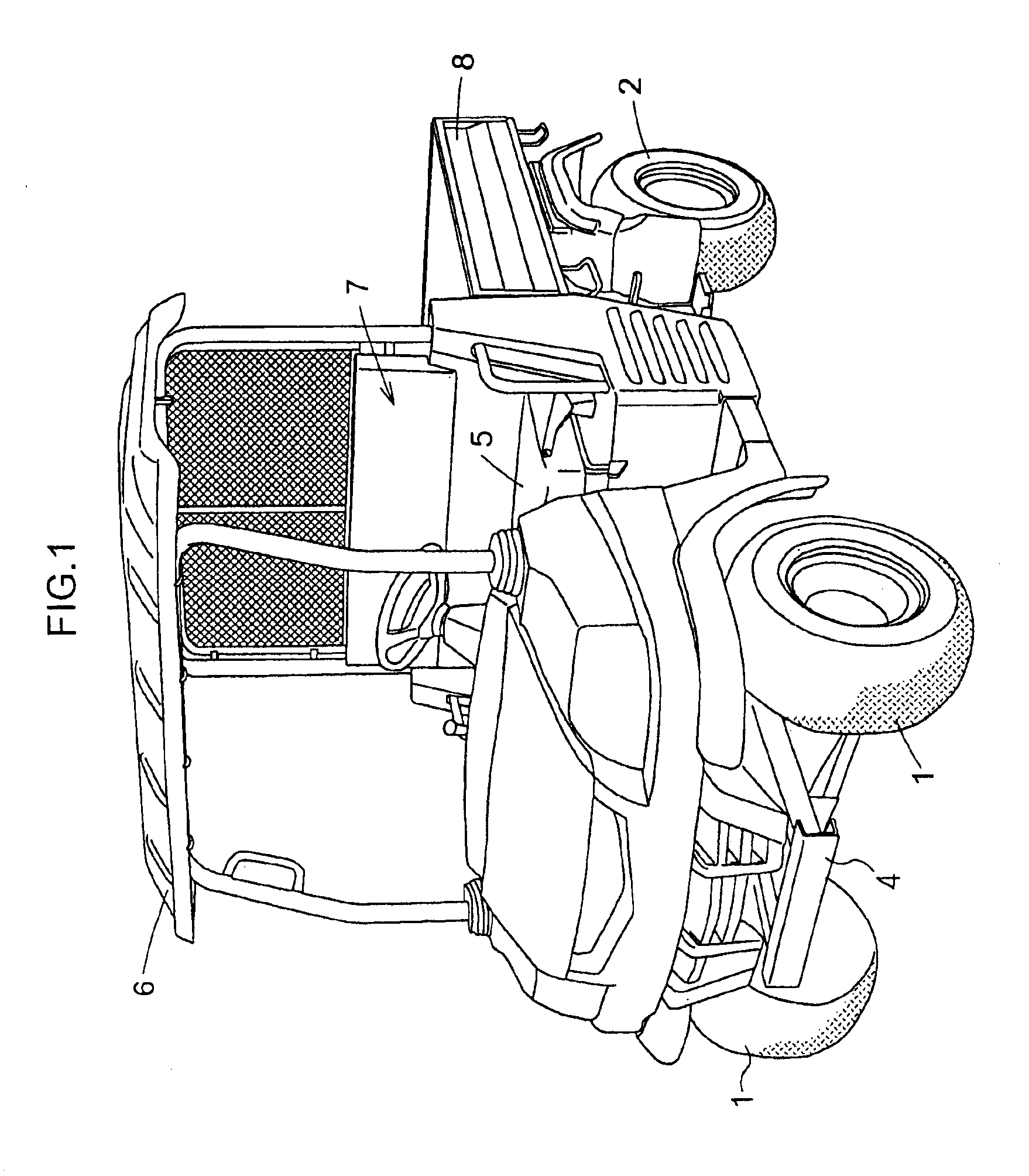
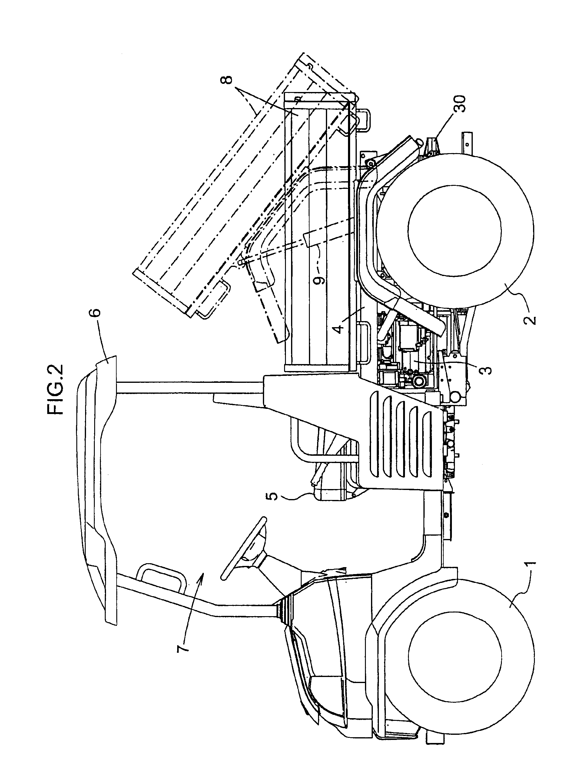
[0025]As shown in FIG. 1, FIG. 2 and FIG. 3, a utility vehicle includes a vehicle chassis 4 supported on the ground by a pair of left and right steerable tired front wheels 1 and a pair of left and right tired rear wheels 2. The chassis 4 mounts, at its front portion and between the front and rear wheels, an engine 3 for driving the front and rear wheels 1, 2. The chassis 4 further mounts, at its front portion, a driver's cabin 7 including a seat 5 and a sunshade 6. The chassis 4 mounts, at its rear portion, a load carrier 8, which is vertically pivotable by a dump cylinder 9 about an axis located rearwardly of the carrier 8 and extending transversely of the vehicle body.

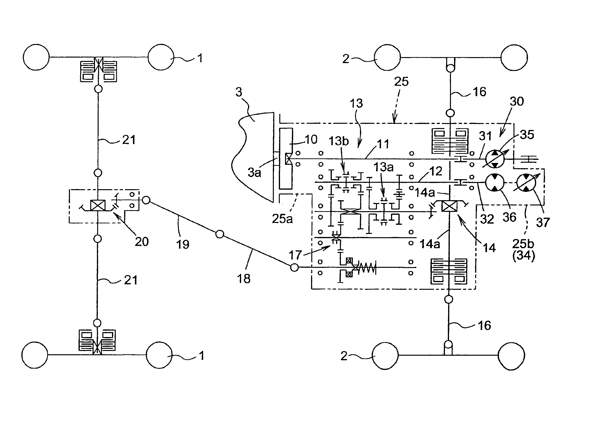
[0026]The power of the engine 3 is transmitted to the front and rear wheels 1, 2 by a traveling transmission unit shown in FIGS. 4 and 5. More particularly, an output from an output shaft 3a attached with a flywheel 10 located rearwardly of the engine 3 is transmitted via a rotational shaft 11 to an input shaft 31 o...


PUM


Abstract

A change-speed control system is provided for a utility vehicle having a stepless change-speed apparatus for speed-changing an engine output and transmitting the speed-changed output to a traveling unit. The system includes an engine speed governor for adjusting speed of the engine, an accelerator controller and a change-speed control linkage device for providing operative displacements in the stepless change-speed apparatus and the engine speed governor in association with an operation of the accelerator controller. The change-speed control linkage device sets an operation amount for the stepless change-speed apparatus and an operation amount for the engine speed governor in correlation with the operation amount of the accelerator controller, such that an acceleration ratio for the engine speed is greater than an acceleration ratio for the stepless change-speed apparatus until the engine reaches a predetermined speed and also the stepless change-speed apparatus reaches a predetermined speed.

Description

BACKGROUND OF THE INVENTION[0001]1. Field of the Invention[0002]The present invention relates to a change-speed control system for a utility vehicle having a stepless change-speed apparatus for speed-changing an engine output and transmitting the speed-changed output to a traveling unit and also a change-speed control linkage device for linking a displacement of an accelerator controller with operations of an engine speed governor and the stepless change-speed apparatus, so that the stepless change-speed apparatus may be operated to an acceleration side in association with an operation of the engine speed governor to the acceleration side.[0003]2. Description of the Related Art[0004]With such change-speed control system as described above, with an operation of the accelerator operation, both an adjustment of the engine speed and an adjustment of speed of the stepless change-speed apparatus can be made. A change-speed control system of this type is known from e.g. the Japanese Patent...

Claims


Application Information

Patent Timeline
Patent Type & Authority Patents(United States)
IPC IPC(8): B60K17/06F02D29/00F02D11/04F16H47/00F16H47/08F16H59/48F02D11/00B60W10/06B60W10/04B60W10/10B60W10/103F16H39/00
CPCB60W10/06B60W10/103B60W30/18027F16H57/04B60W30/1819B60W30/18063Y10S180/90Y10T477/692Y10T74/2186Y10T74/19149A01K61/80
Inventor NAKATANI, YASUNOBUHORIUCHI, YOSHIFUMI
Owner KUBOTA LTD
Why Eureka
Try Eureka