
Pneumatic dedusting device

A pneumatic dust removal and air pipe technology, applied in the direction of charging system, engine components, machine/engine, etc., can solve the problems of affecting the performance of the air filter, blocking the filter hole of the filter, etc., and achieves convenient speed adjustment, simple structure, high efficiency effect

Pending Publication Date: 2017-05-24
天津恩卓尼尔科技有限公司
View PDF8 Cites 3 Cited by
  • Summary
  • Abstract
  • Description
  • Claims
  • Application Information

AI Technical Summary

Problems solved by technology

[0004] Car air filter used for a long time will leave some impurity particles to a certain amount, which will block the filter hole and seriously affect the performance of the air filter

Method used


Image

  • Pneumatic dedusting device

Examples


Embodiment

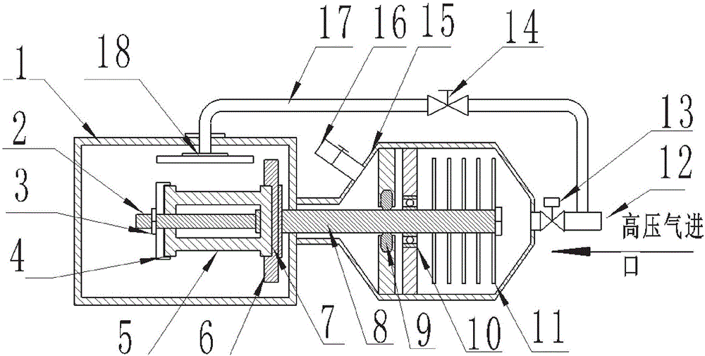
[0020] as attached figure 1 shown

[0021] The present invention provides a pneumatic dust removal device, which includes a cylinder body 1, a screw rod 2, a set nut 3, a gland 4, a filter 5, a turntable 6, a groove 7, a shaft 8, a seal 9, a bearing 10, and an impeller 11 , gas inlet 12, speed control valve 13, valve 14, housing 15, exhaust pipe 16, air pipe 17 and high-pressure nozzle 18; the cylinder 1 is welded on the upper end of the housing 15, and the hollow cavity of the housing 15 is provided with a rotating shaft 8 A seal 9 is installed between the rotating shaft 8 and the housing 15, the bearing 10 sleeved on the rotating shaft 8 is installed on the housing 15, a number of impellers 11 are fixedly connected to the rotating shaft 8, the gas inlet 12 communicates with the air pipe 17, and the air pipe 17 A valve 14 is installed on the top, a groove 7 is provided on the turntable 6, a screw 2 is installed on the upper end of the turntable 6, the bottom base of the filt...


PUM


Abstract

The invention provides a pneumatic dedusting device which comprises a barrel welded to the upper end of a shell. A rotary shaft is arranged in a hollow inner cavity of the shell. A sealing piece is installed between the rotary shaft and the shell. A bearing arranged on the rotary shaft in a sleeving mode is installed on the shell. A plurality of impellers are fixedly connected to the rotary shaft. A gas inlet communicates with a gas tube. A valve is installed on the gas tube. A groove is formed in a turnplate. A screw is installed at the upper end of the turnplate. The pneumatic dedusting device is simple in structure, high-pressure flowing gas is utilized for blowing the impellers to drive the rotary shaft and the turnplate on the rotary shaft to rotate at a high speed, a filter rotates at a high speed while conducting flushing with the high-pressure gas, and the high-pressure gas can cover the surface of the filter quickly; when the filter rotates, impurities inside the filter are hard to gather to the surface of the filter due to the effect of centrifugal force, and the high-pressure gas can quickly blow off the remnant impurities inside the filter; and the cleaning and dedusting efficiency is high, energy is saved, the environment is protected, and the rotating speed is convenient to adjust.

Description

technical field [0001] The invention belongs to the technical field of dust removal processing of automobile filters, and in particular relates to a pneumatic dust removal device. Background technique [0002] Car filters are used to filter impurities or gases. Common car filters include: air filters, air conditioner filters, oil filters, fuel filters, and each corresponding filter is basically Both filter air or liquid impurities. [0003] The function of the air conditioning filter is to filter the air in the car compartment and the air circulation inside and outside the compartment. Remove the air in the compartment or the dust, impurities, smoke odor, pollen, etc. in the air entering the compartment to ensure the health of passengers. At the same time, the air conditioner filter also has the effect of making the windshield difficult to fog. . [0004] If the car air filter is used for a long time, some impurity particles will remain after reaching a certain amount, w...

Claims


Application Information

Patent Timeline
Patent Type & Authority Applications(China)
IPC IPC(8): F02M35/08
CPCF02M35/086
Inventor 杨卓韩雷
Owner 天津恩卓尼尔科技有限公司
Learn More