High-speed recovering treatment device for waste rare earth liquid

A technology for recovery and treatment of waste liquid, applied in the direction of filtration and separation, fixed filter elements, chemical instruments and methods, etc., can solve the problems of rare earth waste liquid filtration stop, etc., and achieve easy maintenance, low manufacturing cost, and convenient operation Effect

Active Publication Date: 2018-04-20
大庆鑫东祥机械制造有限公司
View PDF8 Cites 4 Cited by
  • Summary
  • Abstract
  • Description
  • Claims
  • Application Information

AI Technical Summary

Problems solved by technology

[0005] The present invention overcomes that the existing recovery and treatment devices for rare earth waste liquid usually adopt a traditional structure. After the rare earth waste liquid is filtered, the rare earth collected by filtration needs to be discharged before continuing to filter, resulting in frequent filtration of rare earth waste liquid. Need to stop, so that the rare earth waste liquid cannot be recovered and processed at a high speed. The technical problem to be solved by the present invention is to provide a high-speed recovery and processing device for the rare earth waste liquid

Method used


Image

  • High-speed recovering treatment device for waste rare earth liquid
  • High-speed recovering treatment device for waste rare earth liquid
  • High-speed recovering treatment device for waste rare earth liquid

Examples


Embodiment 1

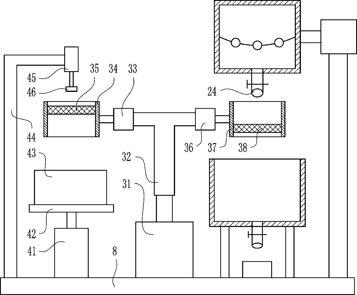
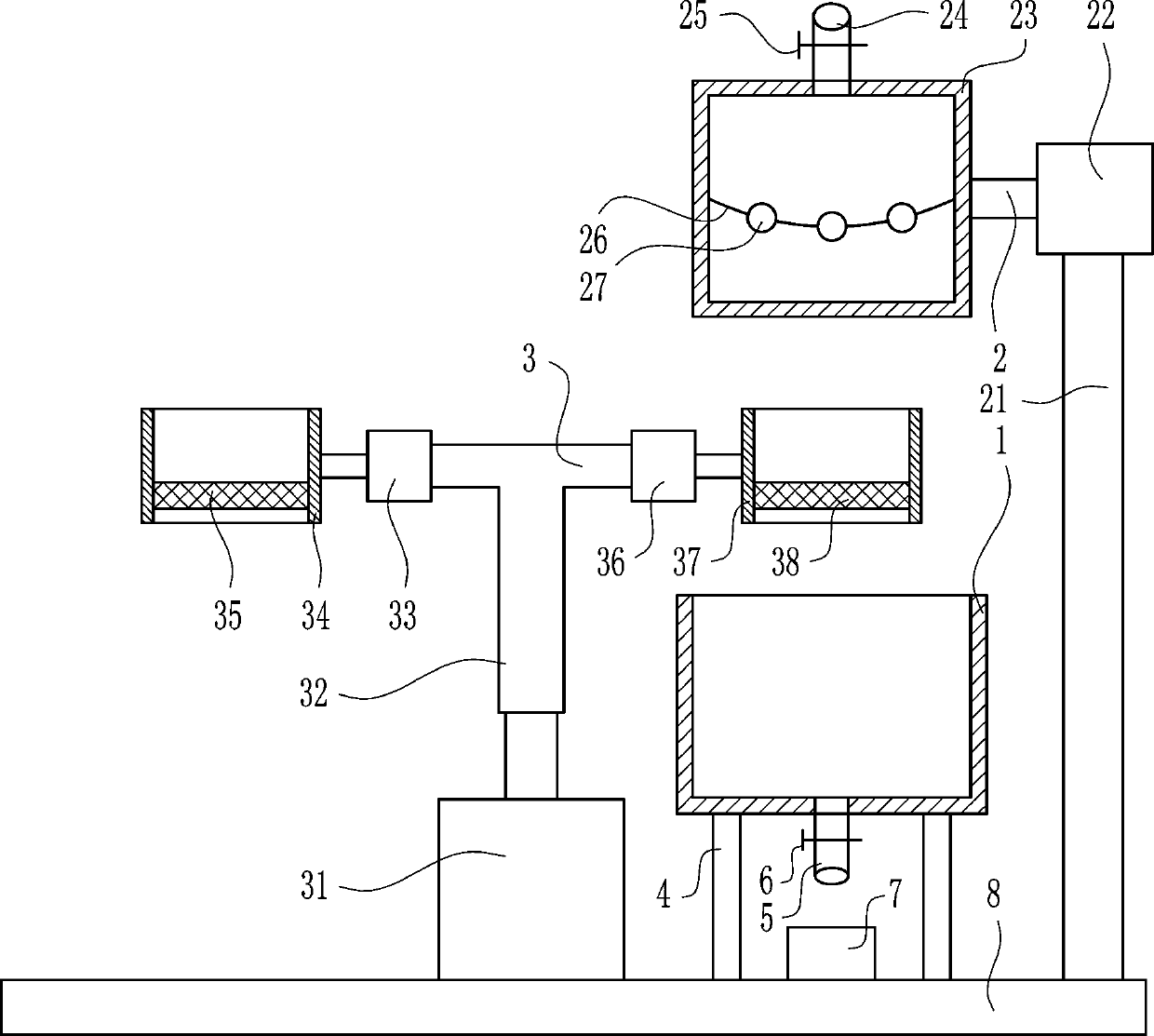
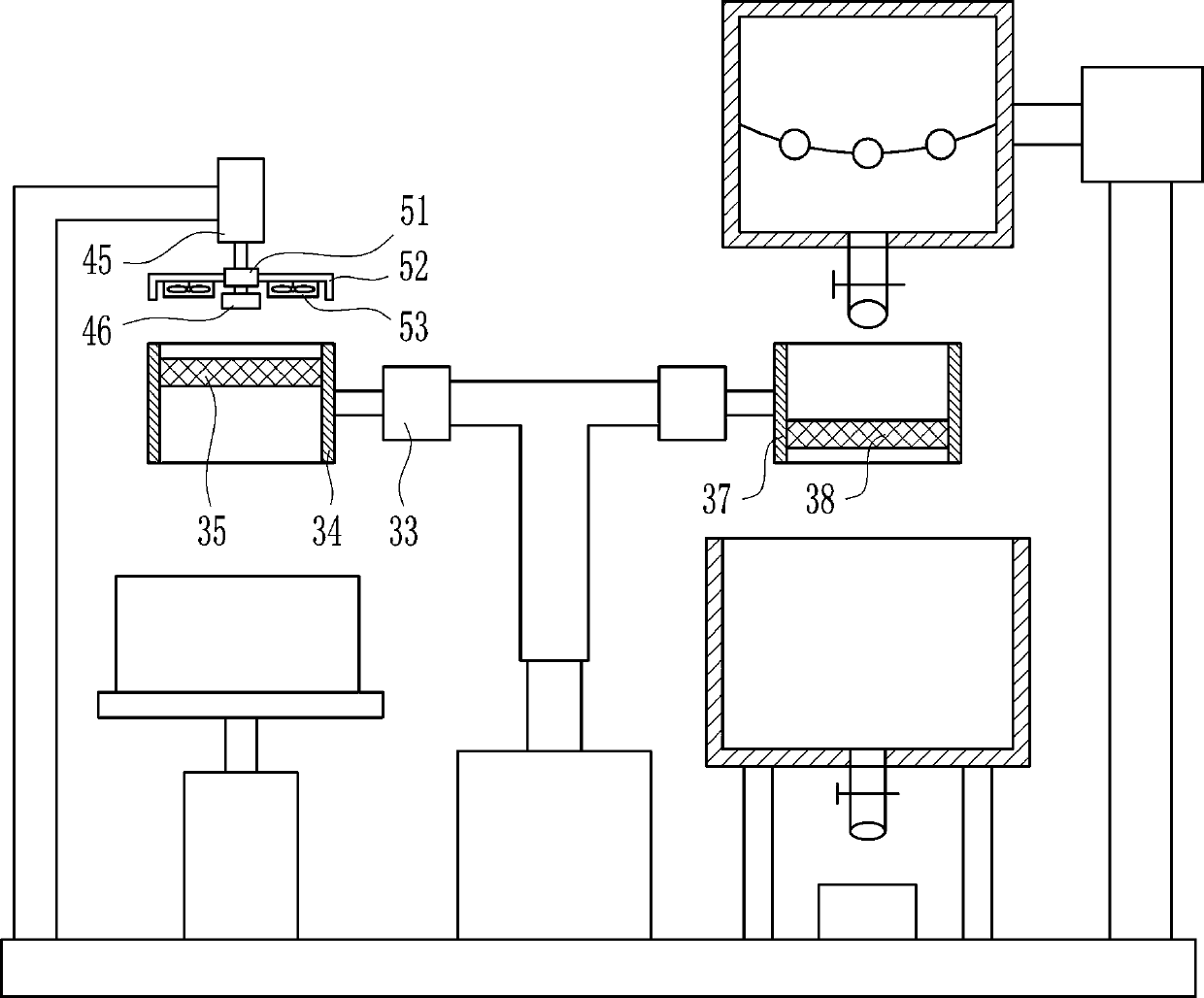
[0027] A high-speed recovery and treatment device for rare earth waste liquid, such as Figure 1-3 As shown, it includes a cylinder 1, a waste liquid stirring and conveying device 2, a filter device 3, a leg 4, a discharge pipe 5, a valve I6, a liquid collection cylinder 7 and a base 8; the upper right of the cylinder 1 is provided with a waste liquid Stirring and conveying device 2, filter device 3 is installed on the left side of cylinder body 1, outriggers 4 are arranged symmetrically on the bottom of cylinder body 1, the upper end of outriggers 4 is connected with the bottom of cylinder body 1 by welding, and the drain The tube 5 is located between the left and right symmetrically arranged legs 4, the upper end of the drain tube 5 is connected to the middle part of the bottom of the cylinder body 1 by welding, the drain tube 5 is connected with the cylinder body 1, and the drain tube 5 is installed There is a valve I6, the liquid receiving cylinder 7 is located directly be...

Embodiment 2

[0029] A high-speed recovery and treatment device for rare earth waste liquid, such as Figure 1-3 As shown, it includes a cylinder 1, a waste liquid stirring and conveying device 2, a filter device 3, a leg 4, a discharge pipe 5, a valve I6, a liquid collection cylinder 7 and a base 8; the upper right of the cylinder 1 is provided with a waste liquid Stirring and conveying device 2, filter device 3 is installed on the left side of cylinder body 1, outriggers 4 are arranged symmetrically on the bottom of cylinder body 1, the upper end of outriggers 4 is connected with the bottom of cylinder body 1 by welding, and the drain The tube 5 is located between the left and right symmetrically arranged legs 4, the upper end of the drain tube 5 is connected to the middle part of the bottom of the cylinder body 1 by welding, the drain tube 5 is connected with the cylinder body 1, and the drain tube 5 is installed There is a valve I6, the liquid receiving cylinder 7 is located directly be...

Embodiment 3

[0032] A high-speed recovery and treatment device for rare earth waste liquid, such as Figure 1-3 As shown, it includes a cylinder 1, a waste liquid stirring and conveying device 2, a filter device 3, a leg 4, a discharge pipe 5, a valve I6, a liquid collection cylinder 7 and a base 8; the upper right of the cylinder 1 is provided with a waste liquid Stirring and conveying device 2, filter device 3 is installed on the left side of cylinder body 1, outriggers 4 are arranged symmetrically on the bottom of cylinder body 1, the upper end of outriggers 4 is connected with the bottom of cylinder body 1 by welding, and the drain The tube 5 is located between the left and right symmetrically arranged legs 4, the upper end of the drain tube 5 is connected to the middle part of the bottom of the cylinder body 1 by welding, the drain tube 5 is connected with the cylinder body 1, and the drain tube 5 is installed There is a valve I6, the liquid receiving cylinder 7 is located directly be...


PUM


Abstract

The invention relates to a recovering treatment device, and in particular relates to a high-speed recovering treatment device for waste rare earth liquid to solve the technical problem. The device comprises a cylinder body, a waste liquid stirring and conveying device, etc., wherein a filtering device is arranged at the left side of the cylinder body; supporting legs are symmetrically arranged atthe lower left and the lower right of the cylinder body; the upper ends of the supporting legs are connected to the bottom part of the cylinder body by welding; a liquid draining pipe is positioned between the supporting legs which are symmetrically arranged at the left and right; the upper end of the liquid draining pipe is connected to the middle part of the bottom part of the cylinder body by welding. According to the device, a mode integrating the waste liquid stirring and conveying device and the filtering device is adopted, so that the waste rare earth liquid can be filtered at high speed without frequent stopping, and as a result, the filtering effect is high, and the effect is good.

Description

technical field [0001] The invention relates to a recovery treatment device, in particular to a high-speed recovery treatment device for rare earth waste liquid. Background technique [0002] Rare earths are known as "industrial vitamins". Now it has become an extremely important strategic resource. Rare earth element oxides refer to oxides of 15 lanthanide elements with atomic numbers from 57 to 71 in the periodic table of elements, and oxides of scandium and yttrium, a total of 17 elements whose chemical properties are similar to lanthanide elements. Rare earth elements have been widely used in petroleum, chemical industry, metallurgy, textile, ceramics, glass, permanent magnet materials and other fields. With the advancement of science and technology and continuous breakthroughs in application technology, the value of rare earth oxides will increase. Rare earths are integral to the manufacture of everything from precision-guided weapons known as "smart bombs" to radar a...

Claims


Application Information

Patent Timeline
Patent Type & Authority Applications(China)
IPC IPC(8): B01D29/03B01D29/96
CPCB01D29/03B01D29/96
Inventor 叶智豪甘丽丹朱清林
Owner 大庆鑫东祥机械制造有限公司
Why Eureka
Try Eureka