High power density alternator bobbin

a high-power density, bobbin technology, applied in the field of bobbins, can solve the problems of reducing the space available for the field coil, requiring a rather large material thickness of the bobbin, and affecting the shape/form/construction of the magnetic circuit, so as to achieve the effect of reducing the size, reducing the material thickness, and increasing the space for the field coil

Inactive Publication Date: 2005-05-03
BORGWARNER INC
View PDF16 Cites 27 Cited by
  • Summary
  • Abstract
  • Description
  • Claims
  • Application Information

AI Technical Summary

Benefits of technology

[0007]The present invention provides a bobbin that can be made very thin, and the end caps can be made of a very durable material. Since the bobbin is decreased in size, there is more space for the field coil and hence more field strength. Further, the heat transfer from the hot copper wires to the cool steel core is increased. Additionally, the strong end caps allow an increased contact force to be applied between the field coil and the pole pieces, increasing the percentage fill of the field coil and increasing the heat transfer between the wires and the pole pieces.

Problems solved by technology

Unfortunately, this design has its drawbacks.
More specifically, the flexibility of the bobbin end caps is due to the material being a generally soft polymer that cannot withstand a lot of contact force created when the bobbin is fit between the pole pieces.
Furthermore, injection molding of the bobbin requires a rather large material thickness of the bobbin.
The thick material inhibits dissipation of heat, and decreases the space available for the field coil.
Thin bobbins cannot be formed because the bobbin mold must fill with molten plastic within a reasonable cycle time.

Method used


Image

  • High power density alternator bobbin
  • High power density alternator bobbin
  • High power density alternator bobbin

Examples


Embodiment Construction

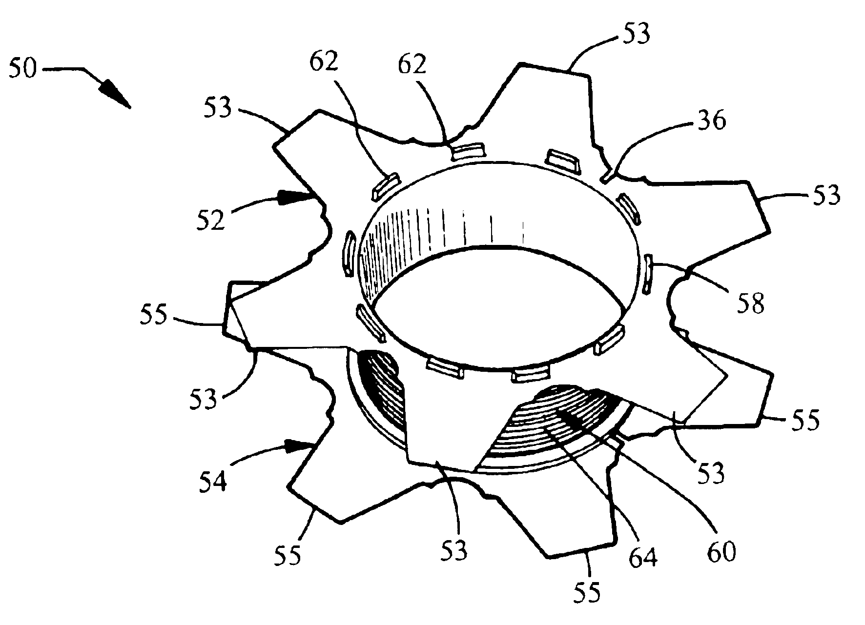
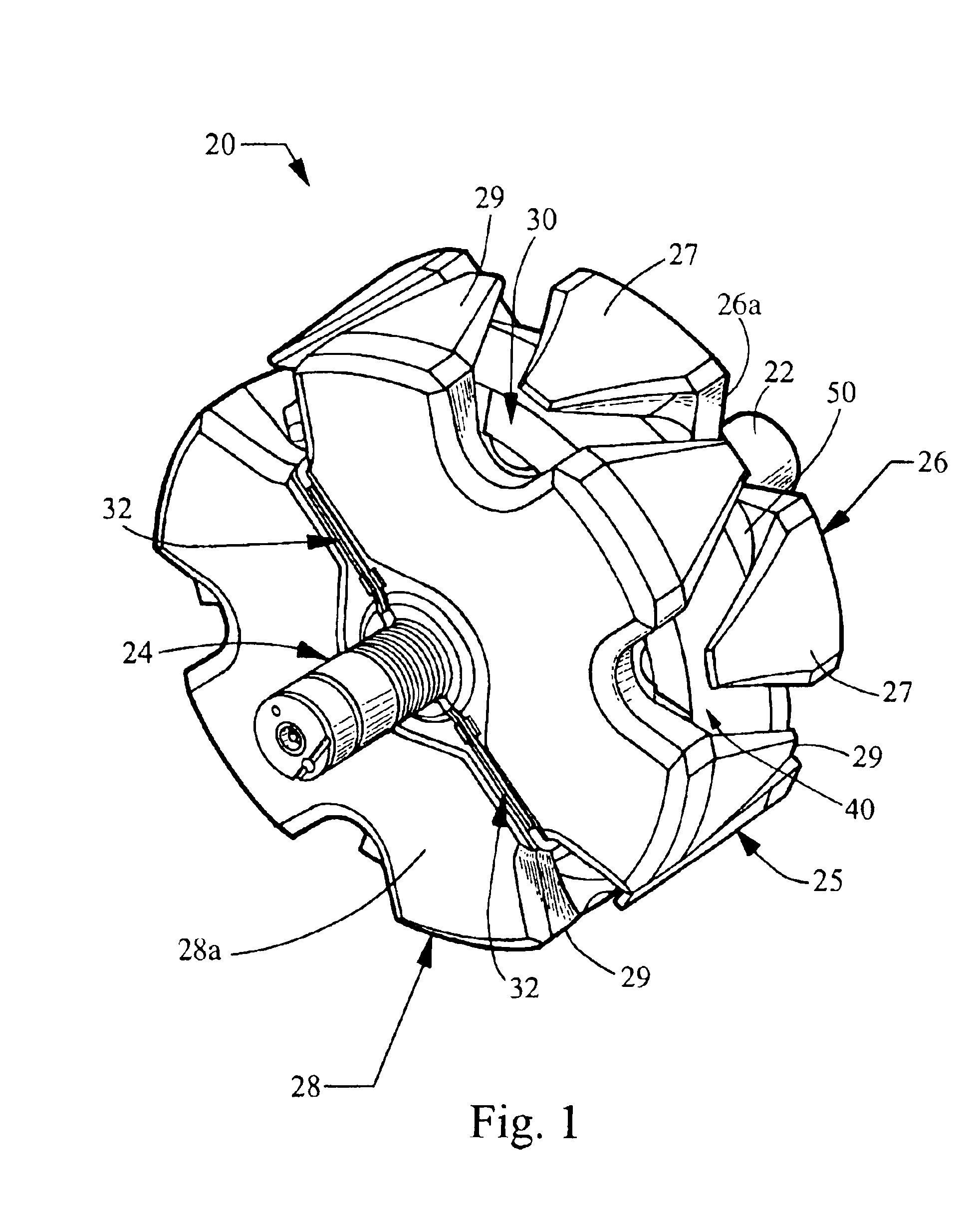
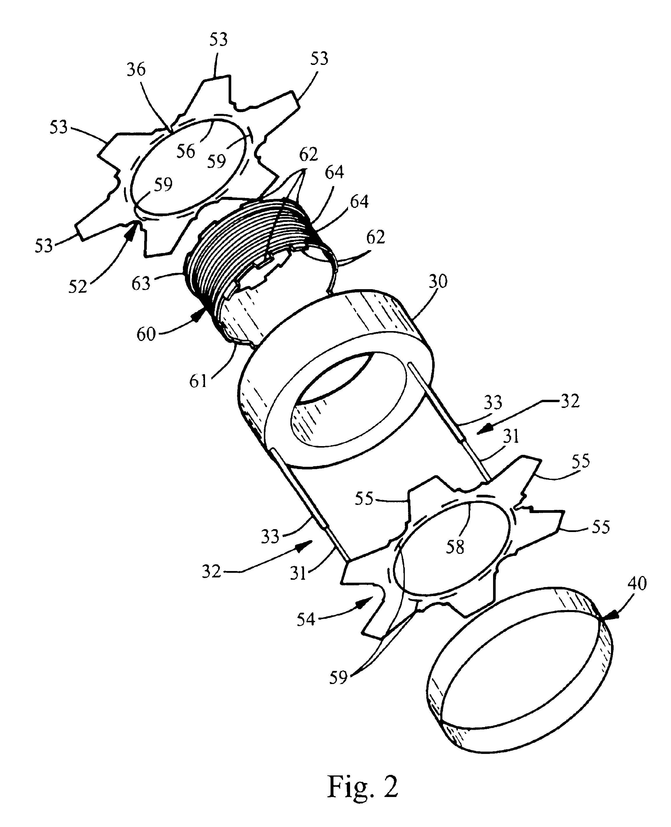
[0016]Turning now to the figures, FIG. 1 shows an assembled rotor 20 having a bobbin 50 constructed according to the invention. Generally, the rotor includes a shaft 22 defining a central axis passing through the center of the rotor and including a slip ring assembly 24 for providing power to the rotor 20. The rotor further includes a first or front pole 26 and a second or rear pole 28. These opposing poles 26, 28 each include a plurality of fingers 27, 29, respectively, which are equidistantly spaced about the periphery of the poles 26, 28. The fingers 27, 29 depend transversely from the main bodies 26a, 28a of the poles 26, 28, and accordingly extend in an axial direction. The fingers 27, 29 thus face each other when the rotor 20 is assembled. Accordingly, the peripheral side surface 25 of the rotor 20 generally alternates between the fingers 27 and fingers 29 of the front pole 26 and the rear pole 28, respectively.

[0017]The poles 26, 28 are used to encase a coil assembly 30 there...


PUM


Abstract

A bobbin for a rotor is of a three-piece construction which allows for greater heat transfer, increased percentage fill, and hence increased power density of the alternator. Preferably, the three-piece assembly includes an injection molded plastic core, and opposing end caps constructed of a laminate material having good tearresistance.

Description

FIELD OF THE INVENTION[0001]The present invention relates generally to rotors for alternators, and more particularly relates to bobbins used in such rotors.BACKGROUND OF THE INVENTION[0002]Currently, the majority of all vehicles driven today use front-end accessory drive alternators that contain Lundell style rotors, also known as “claw pole” rotors. The rotor provides the alternator's magnetic field and rotates within the machine. The rotor includes a field coil made up of a number of insulated copper wires wrapped around an electrically insulated bobbin. The bobbin surrounds a steel hub, and also insulates the field coil from the steel pole pieces which sandwich the field coil to form north and south poles. The magnetic field is generated whenthe field coil is energized and a current flows through the wires.[0003]It is well known that the magnetic field strength that the rotor provides is proportional to the amount of power the alternator can provide to the vehicle system. The fie...

Claims


Application Information

Patent Timeline
Patent Type & Authority Patents(United States)
IPC IPC(8): H02K3/52H02K3/46H02K3/34H02K19/22
CPCH02K3/528
Inventor YORK, MICHAEL T.
Owner BORGWARNER INC
Why Eureka
Try Eureka