Spindle motor and disk drive utilizing the spindle motor

a spindle motor and disk drive technology, applied in the direction of sliding contact bearings, record information storage, instruments, etc., can solve the problems of vibration and worsening non-repeatability run-out, affecting the durability and reliability and the rotational precision of the spindle motor therefore worsening, so as to simplify and slim down the structure of the spindle motor and maintain the effect of rotational stability

Inactive Publication Date: 2005-05-03
NIDEC CORP
View PDF3 Cites 37 Cited by
  • Summary
  • Abstract
  • Description
  • Claims
  • Application Information

AI Technical Summary

Benefits of technology

[0012]An object of the present invention is to simplify and slim down the structure of a spindle motor while maintaining its rotational stability.
[0013]Another object is in a spindle motor to maintain the internal pressure of the oil retained within the bearing gaps at or above atmospheric pressure, to enable preventing the occurrence of air bubbles within the oil.
[0015]A different object of the present invention is to enable preventing particulate matter from being produced due to contact between the rotor and stator components in a spindle motor.
[0016]Moreover, the present invention provides a low-profile, low-cost disk drive that can spin recording disks stably; and another object of the present invention accordingly is to enable preventing the occurrence of read / write errors that originate in oil leaking out from, or in particulate matter being produced by, the spindle motor in a disk drive device.

Problems solved by technology

The volume expansion of the bubbles brings leaking oil toward the exterior of the bearing sections and impairs the spindle motor's durability and reliability.
Furthermore, the dynamic-pressure-generating grooves that are formed in the bearing sections come into contact with the bubbles, which causes vibrations and worsens non-repeatable run-out.
The rotational precision of the spindle motor therefore worsens.
An increased-cost spindle motor is the result.

Method used


Image

  • Spindle motor and disk drive utilizing the spindle motor
  • Spindle motor and disk drive utilizing the spindle motor
  • Spindle motor and disk drive utilizing the spindle motor

Examples


first embodiment

(1) Spindle Motor Configuration

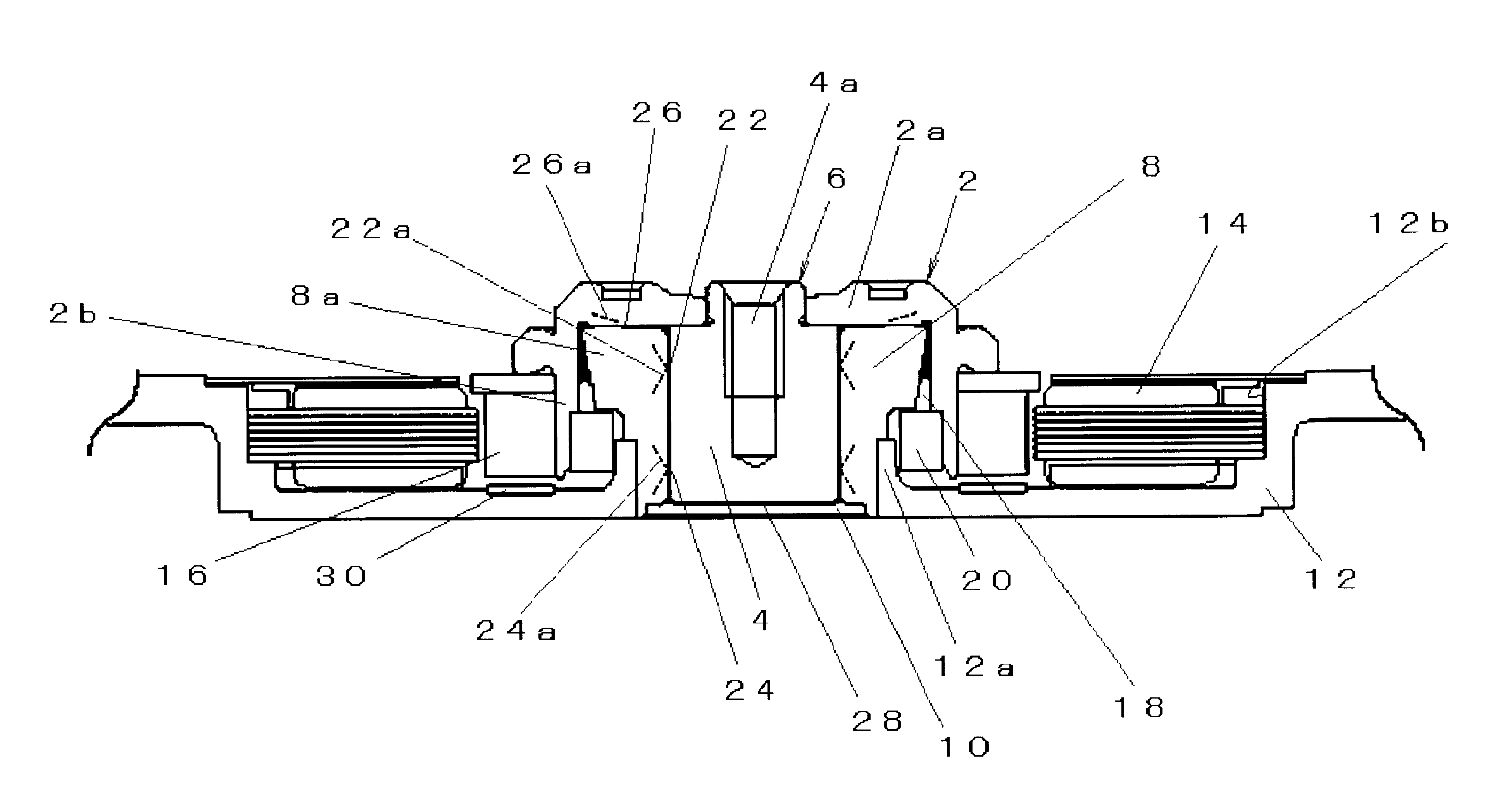
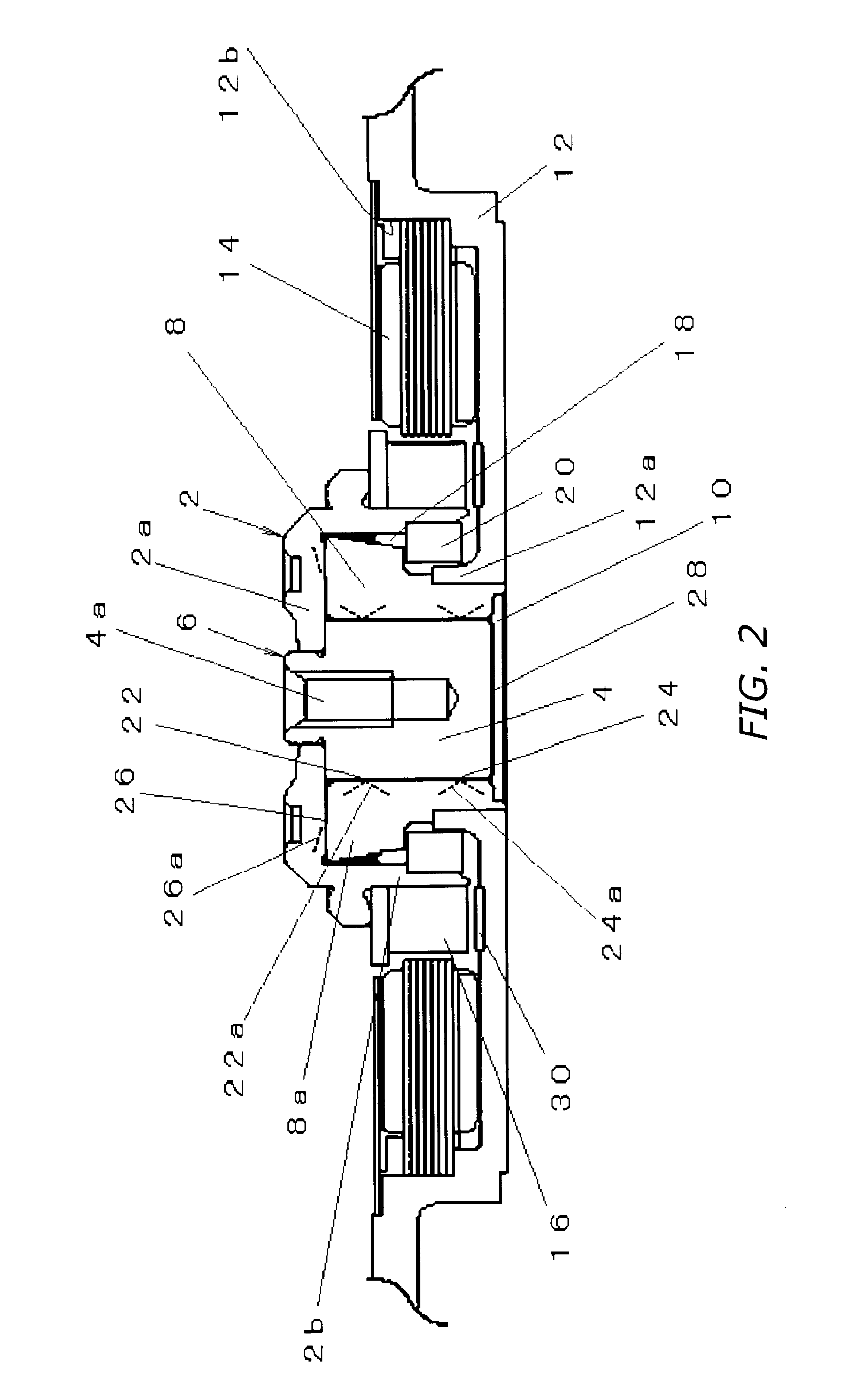
[0032]Reference is made to FIG. 2, which illustrates a spindle motor in a first embodiment of the present invention. Set forth in FIG. 2, the spindle motor is furnished with: a rotor 6 made up of a rotor hub 2—composed of an approximately disk-shaped top wall portion 2a, and a round-cylindrical peripheral wall portion 2b depending downward from the outer rim of the top wall portion 2a—and of a shaft 4 one end portion 4a of which is perimetrically inserted into the central portion of the top wall portion 2a of the rotor hub 2; a hollow, round cylindrical sleeve 8 rotatively supporting the shaft 4; a sealing cap 10 opposing the end face of the shaft 4 along its free end, and closing over the lower portion of the sleeve 8; and a bracket 12 formed integrally with a round cylindrical portion 12a for anchoring the sleeve 8.

[0033]The bracket 12 has a round cupped portion centered on the round cylindrical portion 12a; and a stator 14 having a plurality of teet...

second embodiment

(6) Modified Examples of Second Embodiment

(6-1) Modification Example 1

[0074]In the modification example diagrammed in FIG. 8A herringbone grooves 22a′ formed in an upper radial bearing section 22′ have an asymmetrical configuration in the axial direction, while the herringbone grooves 24a formed in the lower radial bearing section 24 have a symmetrical configuration with respect to where they join, likewise as is the case in the first embodiment.

[0075]To be more specific: In the herringbone grooves 22a′ formed in the upper radial bearing section 22′, spiral grooves 22a′1 located toward the upper end of the sleeve 8 (thrust bearing section 26) are established so as to be longer in axial dimension than spiral grooves 22a′2 located toward the lower radial bearing section 24. Consequently, the place in which the pairs of spiral grooves 22a′1 and 22a′2 join is lower than the center of the upper radial bearing section 22′—i.e., is located biased toward the lower radial bearing section 24....

modification example 2

(6-2) Modification Example 2

[0078]Then as diagrammed in FIG. 8B, it is also possible to render in an axially asymmetrical configuration not only the upper radial bearing section 22′, but also the lower radial bearing section 24′, in a makeup where among the spiral grooves 24a′1 and 24a′2 constituting the herringbone grooves 24a′ formed therein, establishing the spiral grooves 24a′1, located toward the upper radial bearing section 22′, so as to be longer in axial dimension than the spiral grooves 24a′2, located toward the lower end of the sleeve 8, positions the place in which they join biased toward the lower end of the sleeve 8.

[0079]Thus configuring not only the upper radial bearing section 22′ but also the lower radial bearing section 24′ so as induce in the oil a flow heading toward the lower end of the sleeve 8 makes the pressure in the hydrostatic bearing section 28 higher, and strengthens the lifting force on the rotor 6. Because this accordingly makes it so that higher-burde...


PUM

PropertyMeasurementUnit
dynamic-pressure-aaaaaaaaaa
hydrodynamic pressureaaaaaaaaaa
pressureaaaaaaaaaa

Abstract

Low-profile spindle motor whose entire shaft length is utilized to configure, along an encompassing sleeve, a radial dynamic-pressure bearing section. One end of the shaft is unitary with the rotor, and a cover member closes the other end. Between the sleeve upper-end face and the rotor undersurface a thrust bearing section is configured. Micro-gaps are formed continuing between the sleeve upper-end face and the rotor undersurface; the sleeve inner-circumferential surface and the shaft outer-circumferential surface; and the cover member inner face and the shaft end face, where an axial support section is established. Oil continuously fills the micro-gaps, configuring a full-fill hydrodynamic bearing structure. Hydrodynamic pressure-generating grooves in the radial bearing section are configured either so that no axial flow, or so that a unidirectional flow that recirculates from one to the other axial end of the radial bearing section through a communicating pathway is induced in the oil.

Description

[0001]This application CIP of U.S. Ser. No. 10 / 063,929 filed May 27, 2002, now U.S. Pat. No. 6,836,388.BACKGROUND OF INVENTION[0002]1. Technical Field[0003]The present invention relates to spindle motors and disk-drive devices utilizing the spindle motors; in particular to low-profile spindle motors furnished with hydrodynamic bearings, and to disk-drive devices utilizing the spindle motors.[0004]2. Description of Related Art[0005]In hard-disk drives that drive hard disks and like recording disks, spindle motors utilizing hydrodynamic bearings that, in order to support the shaft and sleeve as either one rotates relative to the other, employ the fluid pressure of a lubricating fluid such as oil interposed between the two are known.[0006]With regard to spindle motors utilizing hydrodynamic bearings of this sort, the applicant in the present application has proposed, in Japanese Laid-Open Pat. App. No. 2000-113582, a spindle motor as illustrated in FIG. 1. Between the bottom face of a ...

Claims


Application Information

Patent Timeline
Patent Type & Authority Patents(United States)
IPC IPC(8): G11B25/04G11B17/02G11B17/038G11B17/028
CPCF16C17/107F16C33/107G11B17/028G11B25/043H02K5/1675G11B19/2009F16C2370/12
Inventor NISHIMURA, HIDEKIOKU, YOSHITOYANO, SHINYA
Owner NIDEC CORP
Why Eureka
Try Eureka