
Method of monitoring the power spring of a spring brake actuator

a technology of brake actuator and power spring, which is applied in the direction of brake cylinder, braking system, braking components, etc., can solve the problems of power spring tensile strength loss and power spring defectiveness, and achieve the effect of difficult detection

Active Publication Date: 2005-05-03
INDIAN HEAD INDUSTRIES INC
View PDF13 Cites 25 Cited by
  • Summary
  • Abstract
  • Description
  • Claims
  • Application Information

AI Technical Summary

Benefits of technology

[0009]A preferred method of monitoring the condition of the power spring of a spring brake actuator of this invention includes first calculating a “normal” difference in the push rod stroke as a result of supplying pneumatic pressure to the spring chamber and releasing the pneumatic pressure from the power spring chamber and then comparing the calculated difference in the push rod stroke with the measured difference, which reduces error and provides for determination of the condition of the power spring even if the power spring was defective during manufacture of the spring brake actuator where the stroke of the push rod is determined by a sensor system, the sensor system may also be utilized to signal a defective power spring to the operator or a maintenance person. More specifically, a preferred embodiment of the method of monitoring the power spring of a spring brake actuator of this invention includes determining the stroke of the push rod by a sensor associated with the push rod which either periodically or continuously measures the push rod stroke of the spring brake actuator. The sensor may then signal a computer module or controller which provides the data necessary to compare the push rod stroke resulting by supplying pneumatic pressure to the service chamber and by releasing pneumatic pressure from the spring chamber as described above. In a preferred embodiment, the sensor system further includes a controller, preferably a microprocessor controlled controller, which compares the push rod stroke with a predetermined calculated difference and signals the vehicle operator maintenance person of a defective power spring. Thus, the method of monitoring the condition of a power spring of a pneumatic spring brake actuator of this invention is independent of other conditions of the braking system of the vehicle including, for example, a worn or out of adjustment slack adjuster or foundation brake and other potential failures of the spring brake actuator. Other advantages and meritorious features of the method of monitoring the condition of a power spring of a spring brake actuator of this invention will be more fully understood from the following description of the preferred embodiments, the appended claims and the drawings, a brief description of which follows.

Problems solved by technology

That is, where the stroke of the push rod in the service chamber as a result of the expansion of the power spring is below a predetermined minimum as compared to the stroke of the push rod as a result of supplying pneumatic pressure to the service chamber, the power spring should be considered defective.
As will be understood, a defective power spring may result from loss of tensile strength of the power spring, which may be difficult to detect by simply monitoring the performance of the emergency brake or a broken or cracked power spring.

Method used


Image

  • Method of monitoring the power spring of a spring brake actuator
  • Method of monitoring the power spring of a spring brake actuator
  • Method of monitoring the power spring of a spring brake actuator

Examples


Embodiment Construction

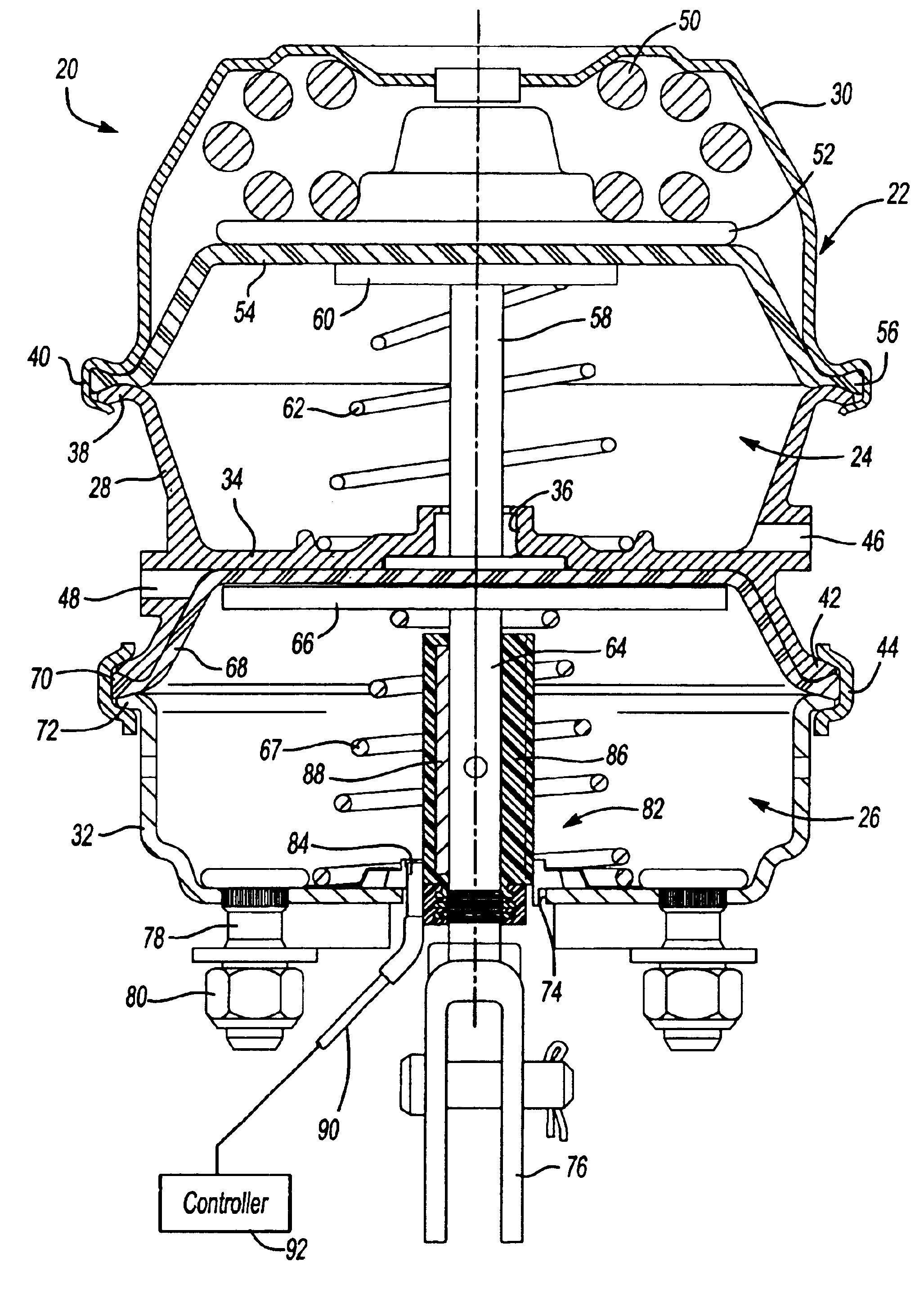
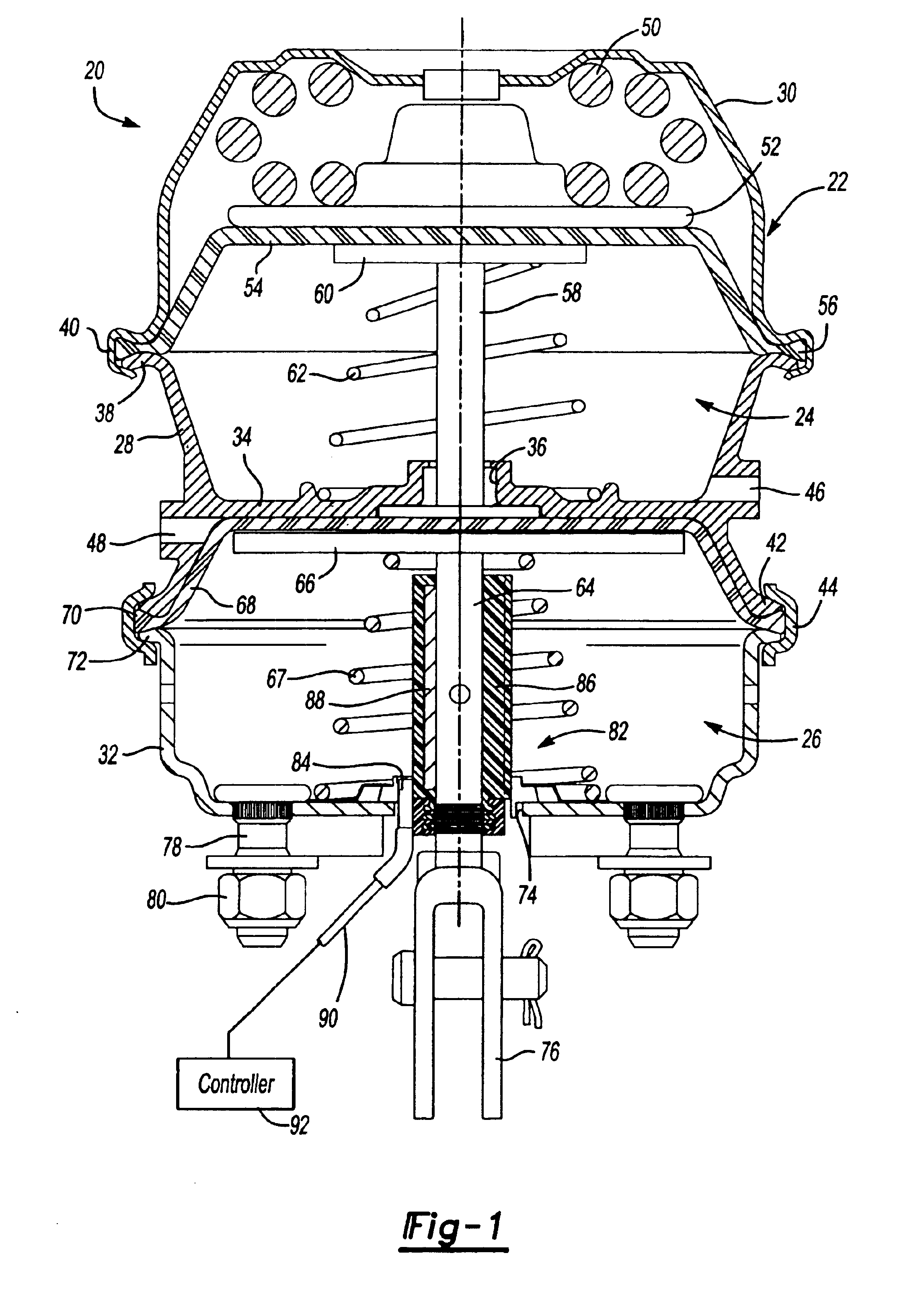
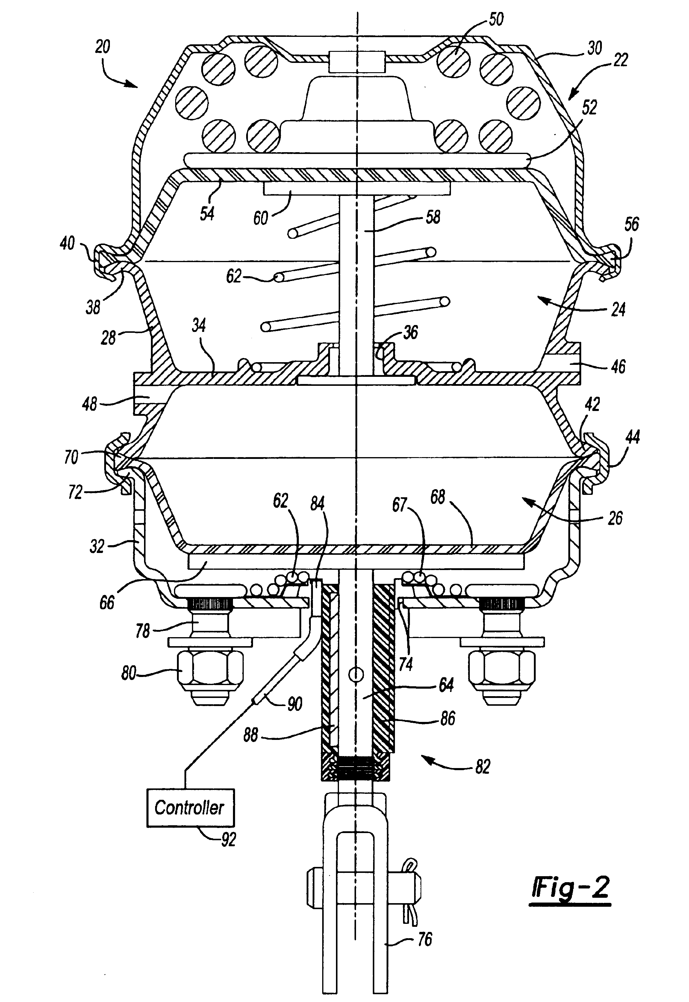
[0014]FIG. 1 illustrates one embodiment of a commercial pneumatically operated spring brake actuator 20 which includes a housing 22 enclosing a spring chamber 24 and a service chamber 26. This type of spring brake actuator is commonly referred to as a “piggyback” spring brake actuator because the spring chamber 24 and service chamber 26 are incorporated in one housing. In the disclosed embodiment, the housing 22 includes a flange case 28, which may be formed from an aluminum casting or other suitable materials, a cup-shaped spring chamber cover or head 30 and a cup-shaped service chamber housing 32. The flange case 22 includes an integral central web portion 34 which separates the spring chamber 24 from the service chamber 26 having a central opening 36, a first radial flange portion 38, which receives an integral skirt portion 40 of the spring chamber head 30, and a second radial portion 42 which typically receives a bolted clamp ring 44. The flange case 22 further includes a pneum...


PUM


Abstract

A method of monitoring the condition of a power spring of a pneumatic spring brake actuator of a vehicle by comparing the stroke of the push rod during normal braking and by actuating the parking brake, wherein a defective power spring is indicated when the difference in the push rod stroke falls below a predetermined minimum. The brake actuator may also include a sensor determining the push rod stroke and signal a defective power spring.

Description

FIELD OF THE INVENTION[0001]This invention relates to a method of monitoring the condition of a power spring of a conventional pneumatic spring brake actuator.BACKGROUND OF THE INVENTION[0002]As set forth below, the power spring of a pneumatic spring brake actuator serves as the emergency brake in the event of failure of the pneumatic braking system of heavy duty vehicles, including trucks, trailers, buses, motor coaches and the like. The power spring also serves as the parking brake for such vehicles. However, there is no industry recognized method of checking the condition of the power spring of a spring brake actuator other than to disassemble the brake actuator. Further, most spring brake actuators are now tamper resistant, such as disclosed in U.S. Pat. No. 4,960,036 assigned to the Assignee of this application, to avoid inadvertent release of the power spring resulting in death or injury. In a tamper resistant spring brake actuator, the power spring chamber is permanently seal...

Claims


Application Information

Patent Timeline
IPC IPC(8): B60T17/00B60T17/08F16D65/14F16D65/28
CPCB60T17/085F16D65/28F16D2066/003F16D2123/00F16D2066/006F16D2121/02F16D2121/12F16D2066/005B60T17/08F16D66/00
Inventor PLANTAN, RONALD S.
Owner INDIAN HEAD INDUSTRIES INC
Learn More